


This post is a tutorial on some of the things you can do to maximize the inexpensive chinese import 7" swing lathes to turn the machines from barely useable to quite capable gunroom tools.
It is NOT intended to be an exhaustive list of the things you can do to make your lathe better, but it does go over some of the most beneficial modifications and tweaks you can do. These lathes can be very capable machines once tuned up a little.
The basic chinese mini-lathe is manufactured by a company in China called "Seig" and the most common model is the 7" swing model C2. It is available in 8, 12 and 14" between center bed lengths. You will nto find the name "Seig" anywhere on these lathes as they are badged for whatever company is re-selling them, but they are all made in the same factory - though some of the small details and options differ from retailer to retailer. These machines are ideal for making screws, turning bushings, working on pistol barrels, and with some changes or modifications to the chuck, they can even be used to thread and chamber barrels with diameters under 0.75".
In Canada, these lathes are sold by Princess Auto and Busy Bee. In the USA
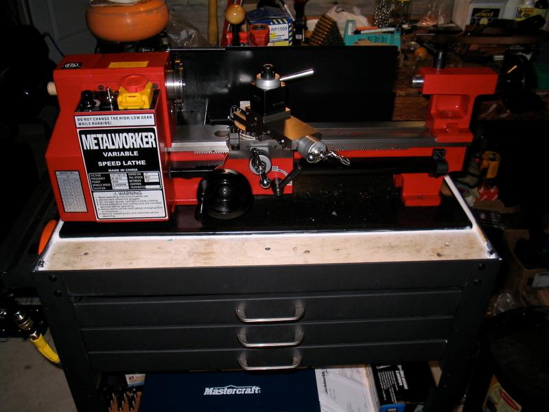
My example came from Princess Auto in Canada, so it's the basic red and black 7x12 C2. This model did not come with way wipes, so I made some up from Aluminum bar stock and used felt pads.
(Click PIC to Enlarge)
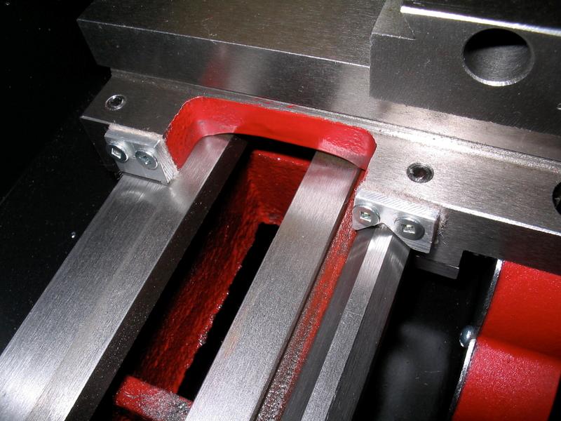
Next, I got tired of cleaning swarf and chips from the apron gears, so I did a very common and useful gear cover mod, only with a twist I haven't seen on other web sites yet. I built my cover from 2mm galvanized steel. I polished the zinc off the inside and lubed the gears up with bearing grease, on the outside I left the zinc intact to discourage surface rust. I cut the basic shape out with a angle grinder after drilling a .70" hole for the apron gear shaft and opened it slightly with a dremel sanding drum for a snug fit. I scribed the basic shape outline and roughed it out with the angle grinder. Final fit with files and patience. It turned out well and worked greatAll holes done in a drill press, tapped by hand. This mod keeps chips from jamming and fouling the apron gears and was the second mod I did to the lathe after way wipes. It has also proved the single most useful mod - bar none.
(Click PIC to Enlarge)
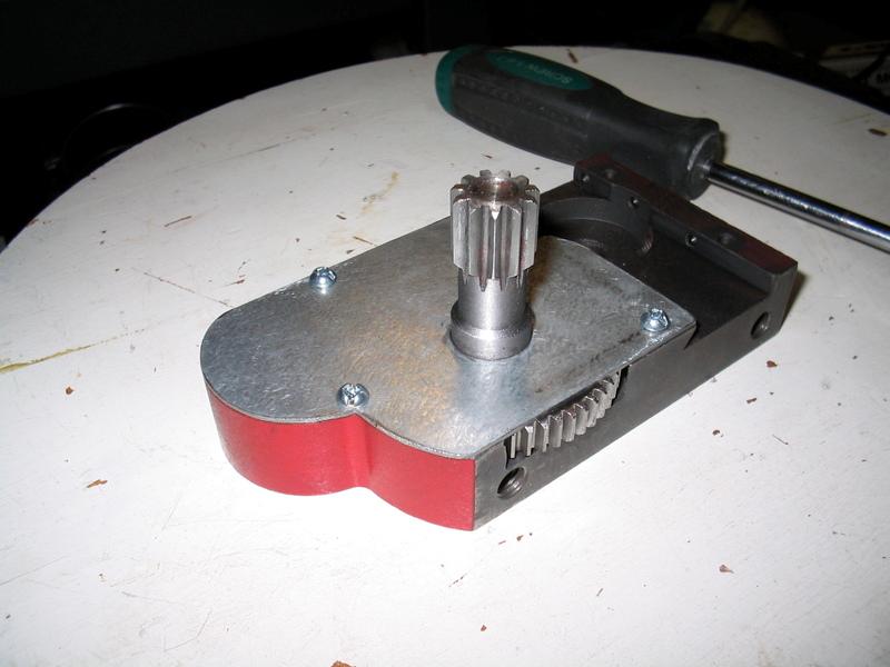
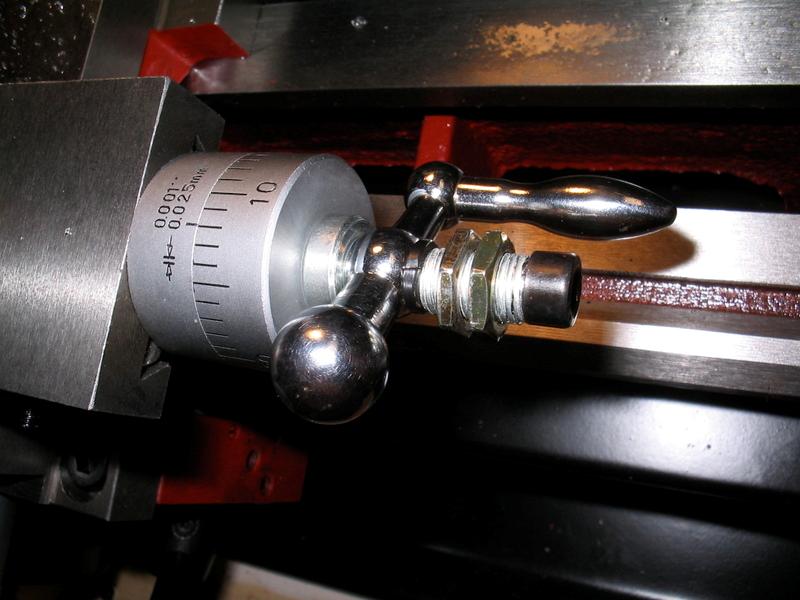
I have also tackled the backlash in the compound slide and modded the compound slide wheel to halt all the knuckle-busting caused by the stock socket-head cap screws.
Here is the stock compound slide setup:
(Click PIC to Enlarge)
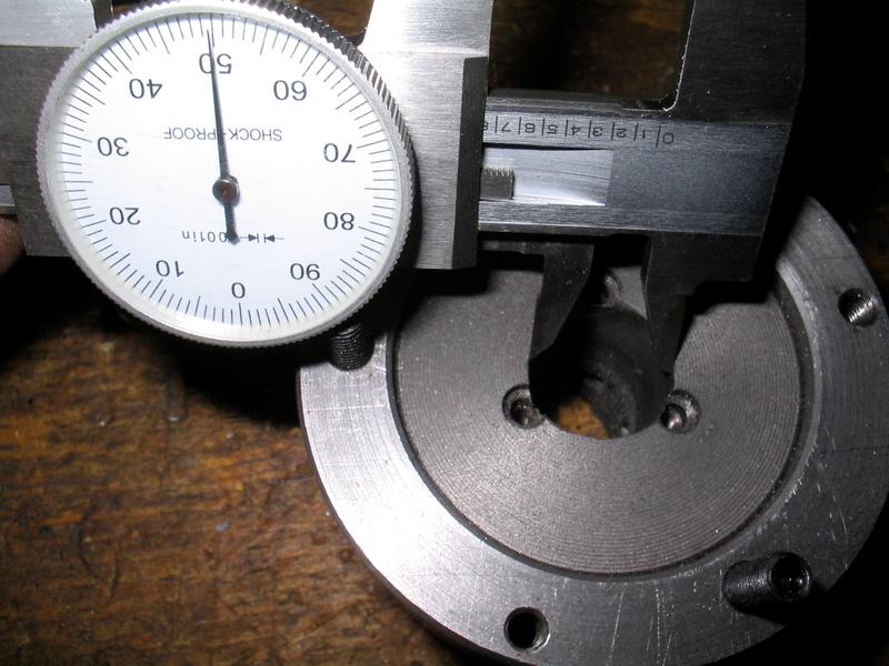
First you need to use feeler gauges to measure the amount of play between the micrometer shaft base and the graduated part of the compound slide micrometer scale. This will represent the backlash introduced by the shoulder in the leadscrew shaft protruding too far past the micrometer scale cylinder. In my case about 5 thou which gets added to any backlash from the leadscrew threads not meshing perfectly with the compound slide base. Let's use an outside caliper to measure the diameter of the leadscrew shoulder. This doesn't need to be exact (it can be a few thou oversize) since the leadscrew shaft centers the handle spacer, not the shoulder.
(Click PIC to Enlarge)
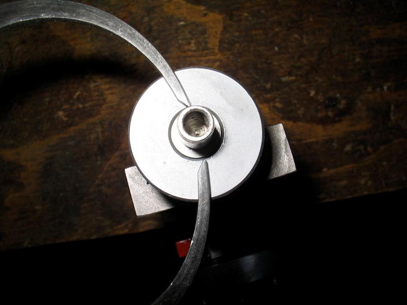
Use a cutter set up for an inside shoulder (in this case an angled carbide cutter) and face a few thou off the inner part of the spacer, leaving a shoulder around the outside edge to act against the micrometer wheel - this will compensate for the overly long leadscrew shoulder (in my case, 5 thou as mentioned earlier)
(Click PIC to Enlarge)
When you re-assemble, this part of the backlash will be gone. My overall compound backlash is now about 1.5 thou which is acceptable.
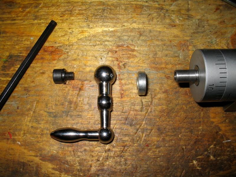
Now let's get rid of that knuckle-busting hex head on the compound. This is the smallest control wheel on the lathe, so it is a real PITA to have such a huge bolt head on it. I cannot claim credit for this mod. I saw the basic concept on a website a few months ago (don't remember which) and I'm a huge copycat if something looks like it will work well.
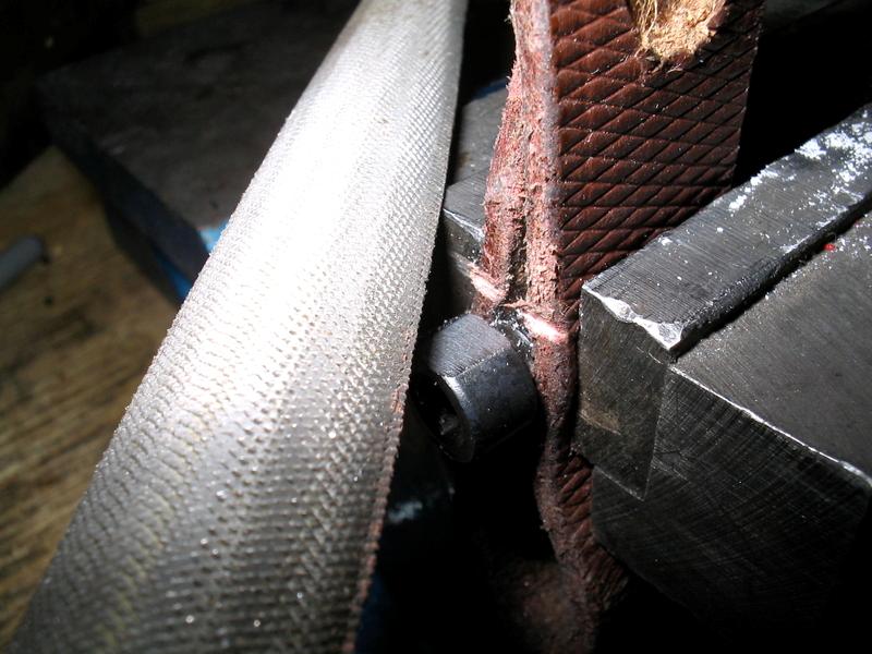
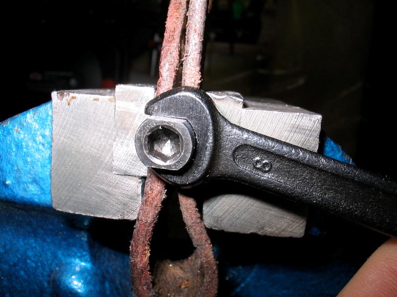
First file flats on the stock bolt to fit the No.8 wrench supplied with the lathe:
(Click PIC to Enlarge)
Go slow and trial fit the wrench often. I held the bolt in the vise with a thick piece of scrap leather to protect threads.
(Click PIC to Enlarge)
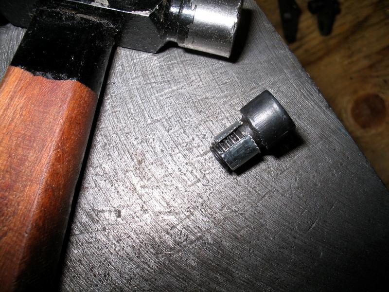
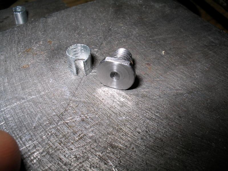
Now using sheet steel and a small ballpeen, make a thread collar to protect the threads from the lathe chuck:
(Click PIC to Enlarge)
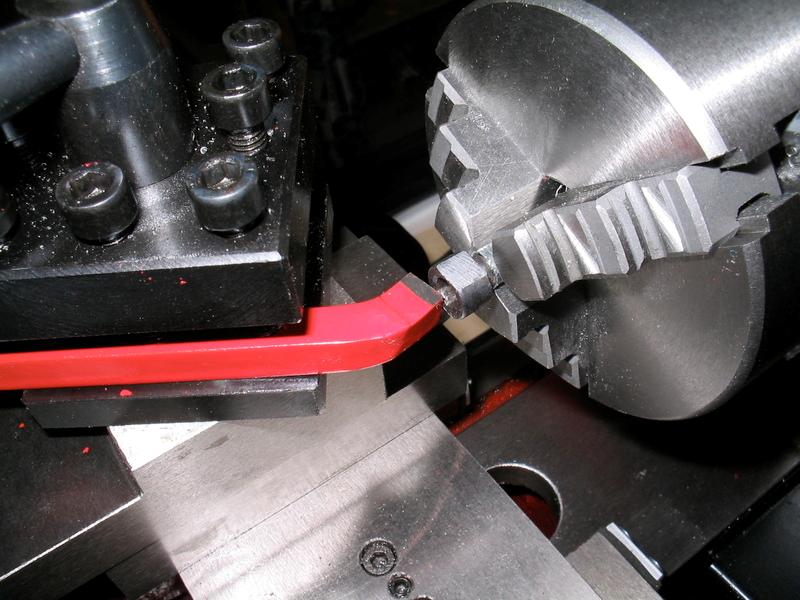
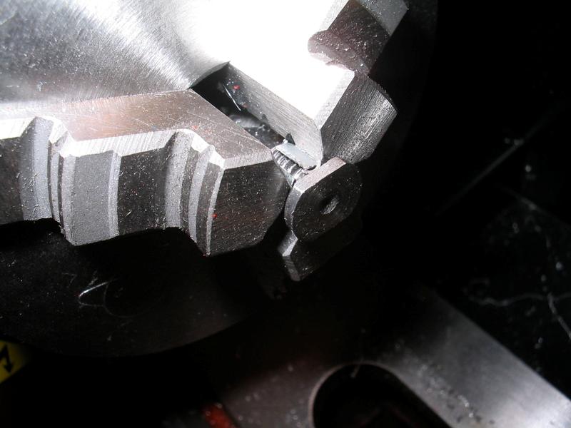
We'll face the bolt off in the lathe...
(Click PIC to Enlarge)
But wait, our compound isn't secured! Well, we'll cheat a little. I removed one of the bolts from the power feed screw pillow block and used a spacer to temporarily replace the compound slide bolt. We'll only be using the power feed screw to lock the saddle in place, so one bolt will be sufficient for this temporary setup.
(Click PIC to Enlarge)
Faced off:
(Click PIC to Enlarge)
Break the edges with a small dressing file and use some wet-dry paper on the head while it's still spinning in the chuck to smooth things off.
(Click PIC to Enlarge)
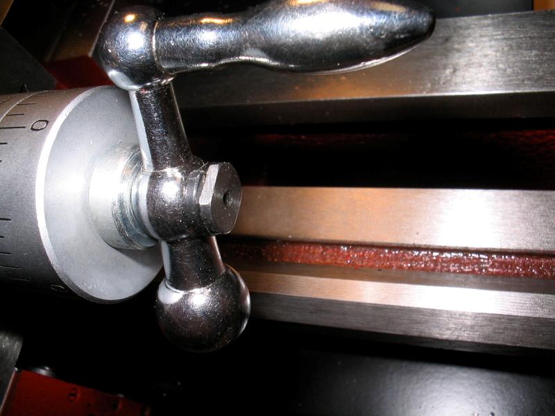
And voila! knuck-buster eliminated!
(Click PIC to Enlarge)
Make sure you slap a little oil onto this bolt head so it doesn't rust.
The C2 lathe typically ships with a (some say undersized) 3" chuck with only a (nominally) 6.5" bore (mine mic'd at 6.40"). Given that the spindle bore is 7/8" (.875") at hte throat with a 0.75 through-bore, this equates to a lot of wasted potential space for turning objects projecting back through the headstock (i.e. barrels).
We can improve it this situation considerably if you still want to keep the 3" chuck. Alternately, if you plan on holding larger objects, a 4" chuck can be purchased along with the suitable chuck adaptor plate. For now we will assume you want to get the most out of the chuck the lathe ships with.
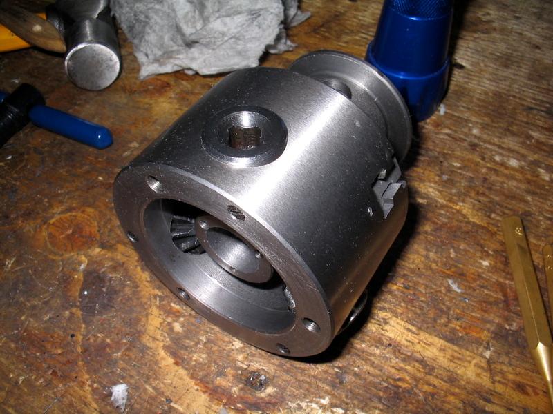
Step 1: Strip the chuck down. While it's apart, thoroughly degrease everything.
(Click PIC to Enlarge)
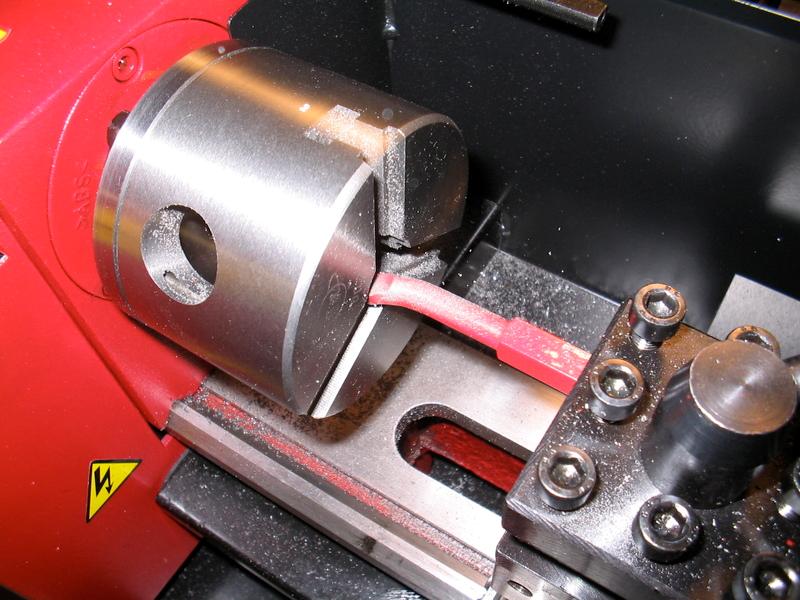
Step2: Mount the empty chuck body back onto the spindle. Chuck up an appropriate boring bar (in this case a carbide tipped borign bar with the rake ground back sharper to fit the small ID of the chuck)
(Click PIC to Enlarge)
Step3: Turn the bore out to 0.75", shich is about the most you can go without breaking into the rear cap retainer screw threads or having the chuck jaw tightening gears breaking through into the bore of the chuck. Use power feed for a decent finish.
(Click PIC to Enlarge)
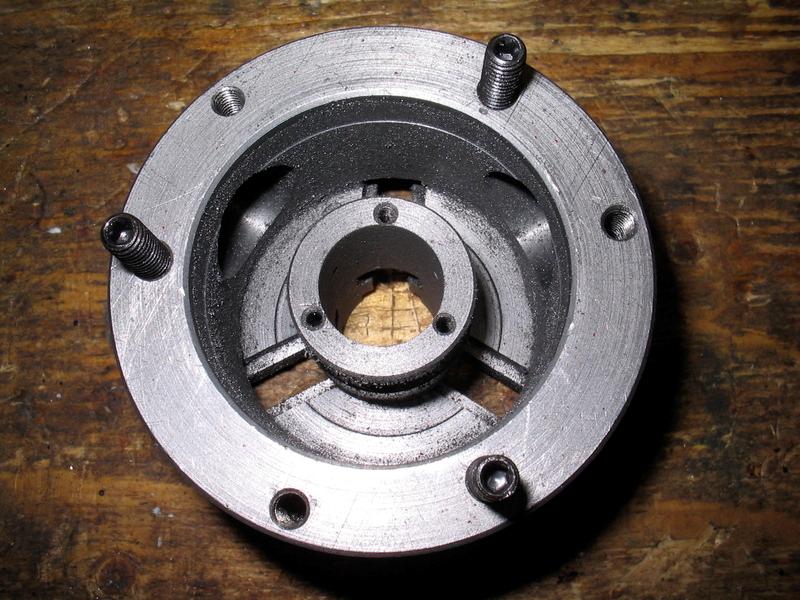
See what I mean about those rear cap retainer screw holes?
(Click PIC to Enlarge)
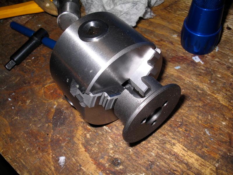
Now assuming you have a new lathe, very likely your 4 jaw chuck has not yet been purchased, or is in the mail. So how are we going to machine the back plate? You cannot install it and ream cuncurrently with the chuck body because the retainer screws are hardenend and won't cut consistently when you bore the back plate. No problem. While still THOROUGHLY DEGREASED, re-aseemble the chuck but leave the backplate off. Use it to hold the backplate. Typically, you wouldn't want to run a chuck this way, but cast iron swarf is powder, not hard chips, and we're only doing one small boring operation. No harm, no foul.
(Click PIC to Enlarge)
Here we go... 0.75". Not perfect, but it's as good as we're going to do without going to a 4" chuck and losing 1/4" or more of bed travel to an adaptor plate.
(Click PIC to Enlarge)
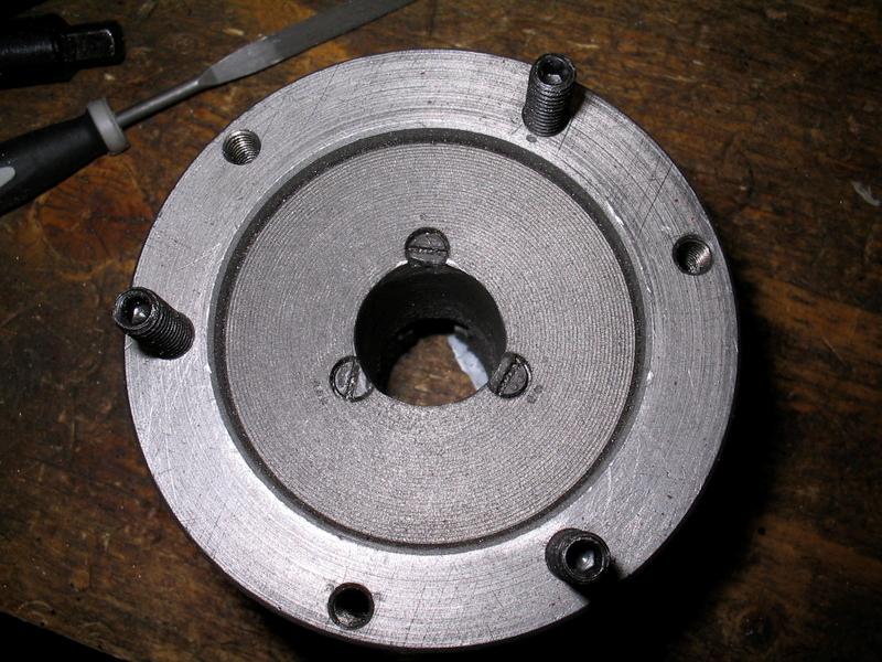
Next, install the backplate screws. I used a punch to mark each screw ., .., & ... and then made corresponding markings in the back plate so the screws will index. Tighten them right down and then use a small grinding wheel on the dremel to make dish cuts in the screw edges so they do not overhang into the chuck bore.
(Click PIC to Enlarge)
Finally, re-mount the empty chuck onto the spindle and make a small 45 degree chamfer to the face of the chuck bore to break the sharp edge. Carefully dress this cut with a fine convex metal file.
(Click PIC to Enlarge)
Re-assemble and enjoy the freedom of a bigger chuck bore. (Clean out all the swarf and re-oil your chuck parts first!)
Finally, you will note in some of the photos I have used number stamps to punch the jaw number next to the slot for each jaw. From the factory these numbers are stamped into the machined slots, but are next to impossible to read when the chuck is on the spindle. This is a super-easy to do mod that makes changing chuck jaws much easier. Some websites advocate using punches much like I did on the back plate screws, ., .. & ..., but a $4 set of number punches does a much cleaner job.
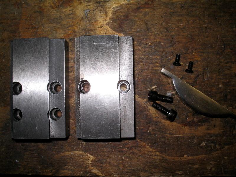
Another mod much talked about on the net is to re-machine the compound slide base to decrease the moment (torque) about the compound side swivel, thus reducing chatter when machining harder steels. If you have a mill, you can do this modification yourself. If not, LittleMachineShop.com - tooling, parts, and accessories for bench top machinists (LMS hereafter) sells a replacement compound slide base already so modified. You do not need to do this modification unless you experience chatter due to a flexing compound slide swivel, but in case you do, here is a picture of the modified slide base next to an original (modded base on the left):
(Click PIC to Enlarge)
Next, I've installed the carriage lock, also from LMS. It's a well designed and well made part. It also WILL scrape off any red paint you may have missed when cleaning up the underside of the bed rails.
(Click PIC to Enlarge)
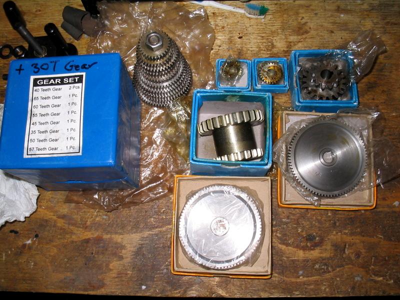
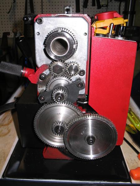
If you plan to do alot of machining on steel, I highly recommend eliminating all the plastic parts from the geartrain except for the motor's belt drive pinion (keep that as a "sacrifical gear"). I got my set from Hobbyist Machine Store (click here)
(Click PIC to Enlarge)
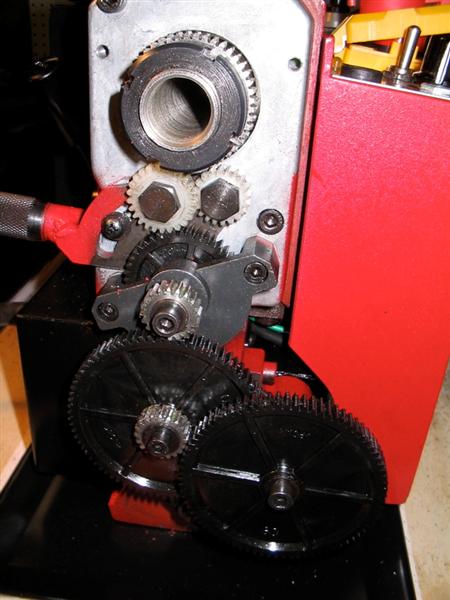
Before starting the task of swapping in all the steel gears, TAKE A PICTURE! It helps to put it all back together!
(Click PIC to Enlarge)
Then start tearing down the gear train...
(Click PIC to Enlarge)
After you pull the motor, you get access to a third mounting bolt needed to remove the headstock.
(Click PIC to Enlarge)
Now she's all in pieces.
(Click PIC to Enlarge)
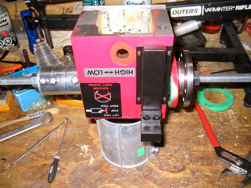
Stock headstock:
(Click PIC to Enlarge)
Now, to remove the headstock spindle, there are two commercial tools available. One is available from LMS, it's well made, but it's a bit overkill if you are only doing one headstock IMHO. The other comes with the headstock gear replacement kit LMS and Micro Mark sells, but my gears came from the Hobbyist Machine Store along with a full metal set of change gears so I was on my own for tooling.
(Click PIC to Enlarge)
The idea is to draw the spindle assembly out of the headstock bearings. The lower spindle comes out easily with a rubber mallet and a pair of snap ring pliers, but the spindle itself is SNUG.
I used some conduit couplings, a 1/4" steel plate with a 1/2" drilled hole in it, some 1/2" threaded rod, some washers and two nuts. Position the bits and use a wrench to turn the nut, it will draw out the spindle along with the flange-side bearing.
(Click PIC to Enlarge)
You need a smaller diameter coupling to put the spindle back in. Make sure is bears on the solid part of the bearing and not the grease shield or you will collapse the headstock bearing - NOT GOOD.
(Click PIC to Enlarge)
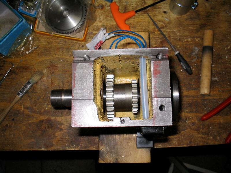
Ta-da!
(Click PIC to Enlarge)
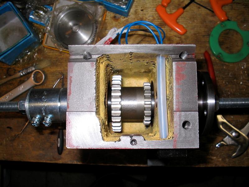
Make sure you grease the gears well, you won't have easy access again once the headstock is re-installed.
(Click PIC to Enlarge)
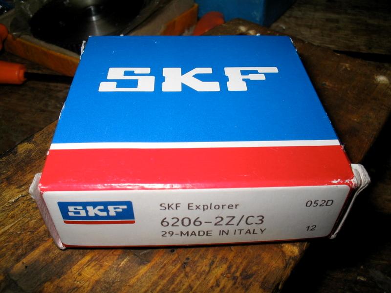
While I was at it, I decided to replace the cheapo Chinese bearings with some nice precision Italian
(Click PIC to Enlarge)
Time for gear erector set:
(Click PIC to Enlarge)
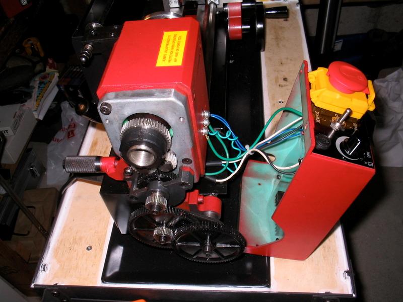
All gears changed out:
(Click PIC to Enlarge)
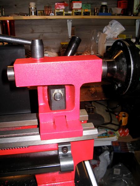
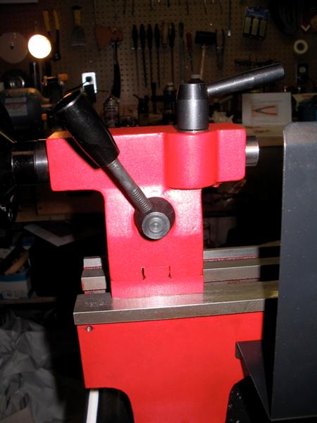
I also decided to modify the tailstock to cam-lock. This is a real timesaving modification if your version of the C2 did not come with it. I used an off-the-shelf conversion kit from LMS:
(Click PIC to Enlarge)
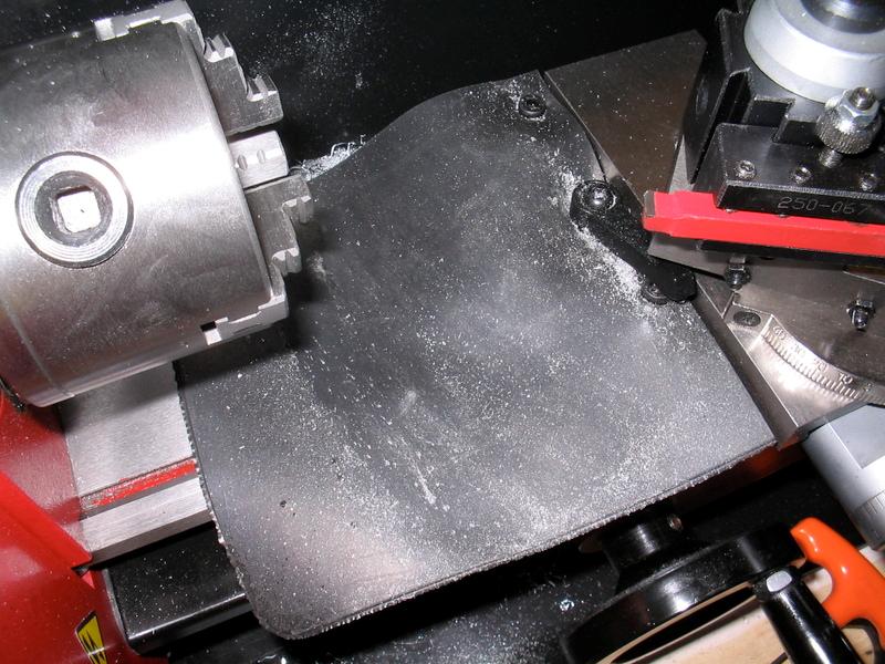
And here is my chip flap solution. Basically, I used real rubber and cut the holes so that they are tight on the screw heads for the carriage lock and the lock lever also goes through a slightly undersized hole. The rubber is tight enough on these parts that it easily stays in place. This minimizes the amount of chips & swarf the way wipes have to deal with by protecting the ways.
(Click PIC to Enlarge)
The next modofication I did was to replace the plastic apron hand wheel with a new one machined from 6061 Aluminum. It is more rigid and not likely to strip the handle threads like the stock wheel is prone to having happen.
Here are the pics in case anyone else wants to do the same:
A 4.5" bar of 6061 JUST fits the Seig 3" 4 Jaw chuck (purchased from LMS).
(Click PIC to Enlarge)
To create the base collar, you can either repeatedly face the workpiece down to diameter, or you can turn it to diameter. I decided to face to ensure I didn't remove too much from the part that would become the wheel. This project generates ALOT of chips and I had to remove the chip guard to use all the cross-slide travel (the stock chip guard limits travel). A better solution would be to sand-cast a wheel and finish machine it, but I am not set up for sand casting - sadly.
(Click PIC to Enlarge)
Once you have the depth machined, you turn the base collar. Dimensions of the base collar are simply copied from the original plastic hand wheel, but my aluminum stock was slightly too thin, so I used a 15 degree web bevel. The original was about 30 degrees. In the end, it doesn't make much difference so long as you leave enough thickness at the center to enclose the entire gear pin on the apron. In my design, the wheel protrudes about 1/4" less than the stock wheel.
(Click PIC to Enlarge)
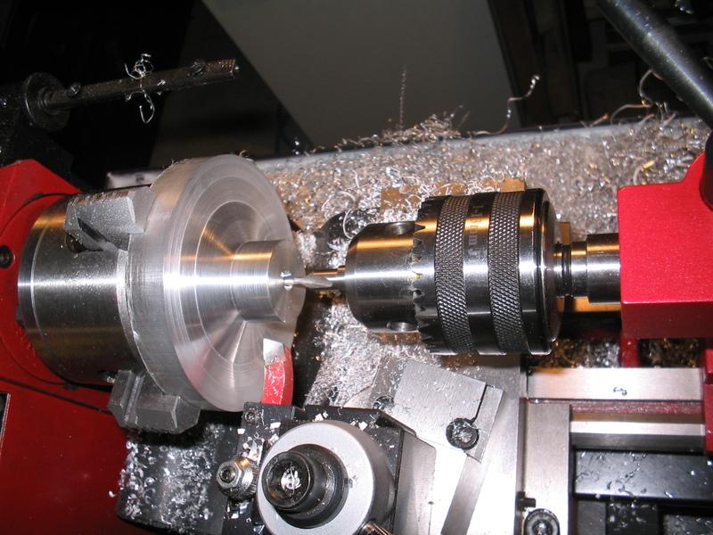
While the piece is still clamped in the 4-jaw, I center-drilled the base and then drilled out the new hand wheel to the same diameter as the original. When drilling aluminum, back the drill out every 2 diameters of depth and clean off the swarf to prevent galling in the hole. Use a decent cutting oil too. I prefer Lenox myself, but they all work OK.
(Click PIC to Enlarge)
While still in the 4 jaw, turn the protruding stock down to finished diameter, then flip the part around, clamp it in the 3 jaw using the newly machined base collar and then machine the rest to size. You'll notice the bevel for the web, it was cut at 15% using the compound.
(Click PIC to Enlarge)
The front was faced to proper thickness, then a 1/4" step machined into the face. Another 15 degree bevel was cut from the base of the step to the depth that the apron pin protrudes - this creates the web of the wheel. Once you reach the appropriate depth, you machine a flat and face it over to the shaft hole. Finally, you turn the new wheel very fast and polish it with 220 and then 600 grit. Here you see it trial fitted. Perfect!
(Click PIC to Enlarge)
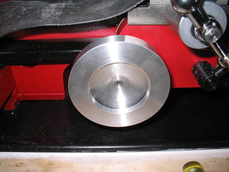
Here is the machined wheel next to a piece of stock identical to the one I used.
(Click PIC to Enlarge)
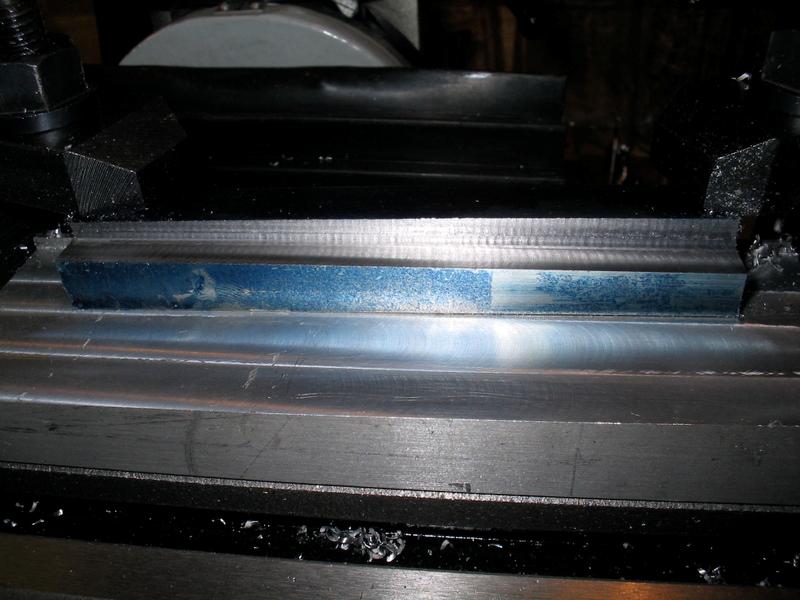
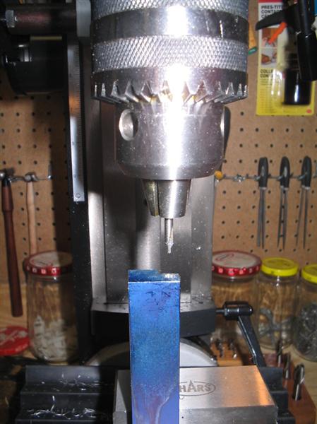
The locking screw hole was done on a drill press with keystock blocks used as spacers so the finish wouldn't get dinged up. The original lock screw was re-used. It is an M6x1.0 screw, so use a No.6 drill and the appropriate metric tap. Use cutting oil!! I actually badly twisted a cheap chinese tap while tapping this deep hole and had to go buy a decent american made Irwin M6x1.0 tap to finish the hole. Cheap import taps suck - unfortunately.
(Click PIC to Enlarge)
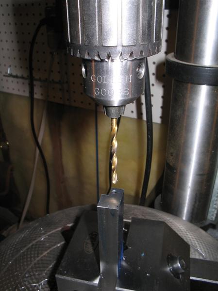
Finally, the stock handle was fitted. I will eventually replace it with an Aluminum handle, but am not in a hurry. The hole was again drilled on a drill press using a 3" toolmaker's vise. The hole is a M8x1.25 thread.
Hope that helps someone.
(Click PIC to Enlarge)
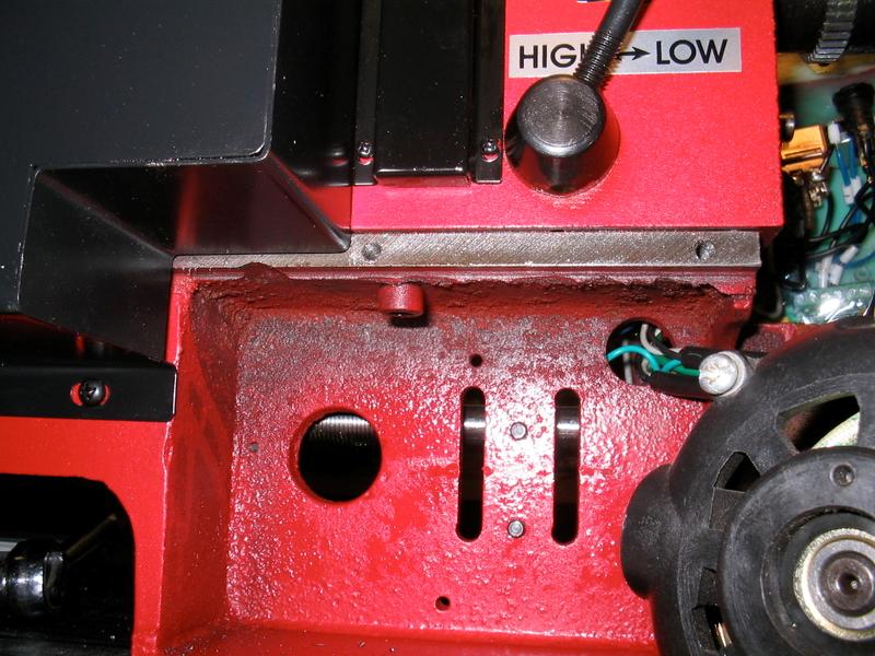
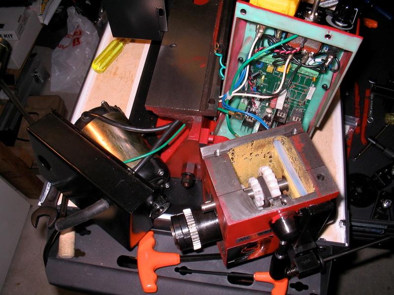
Here is another mod I just did to address an annoying problem with the mini-lathe. Seig, for reasons unknown, left the spindle open inside the gear enclosure. End result = chips constantly falling into the change gears and causing grinding & wear. Furthermore, on my version of the C2, the opening to the spindle through the gear box was covered with a sheet metal disk and two bolts. Not sure why, but if anything this served to ensure those chips didn't miss the gears.
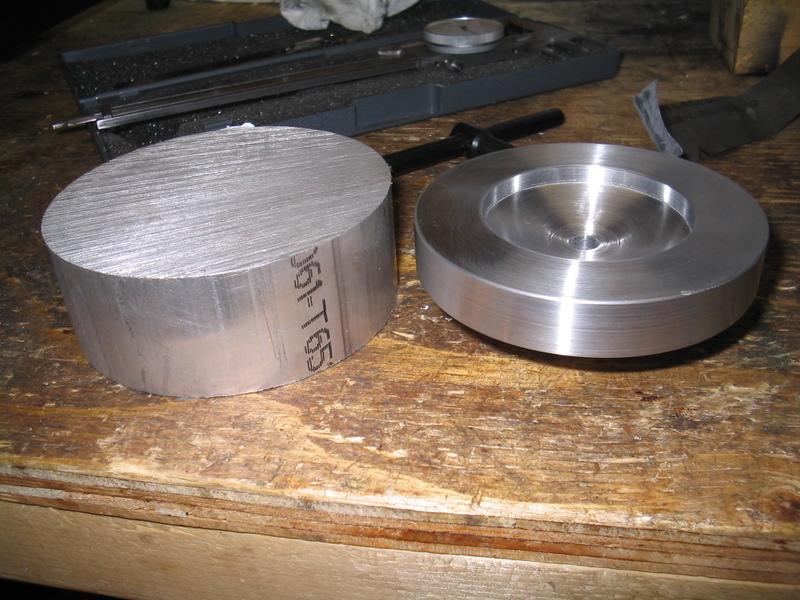
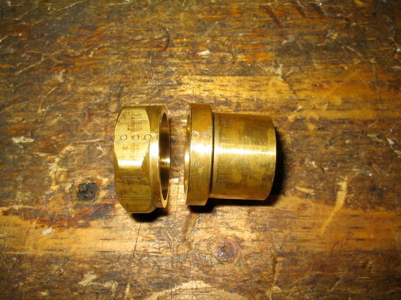
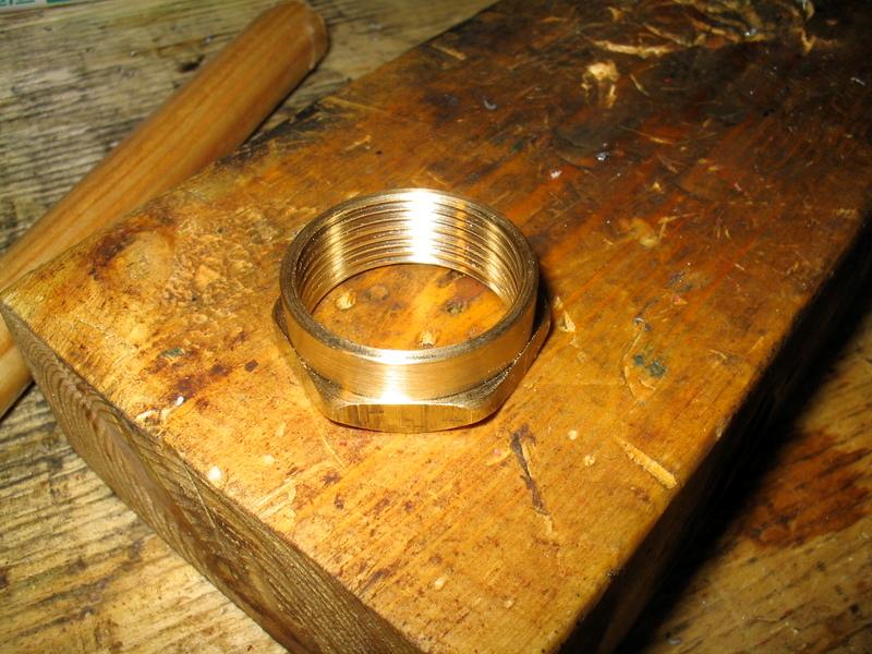
I went to the hardware store and bought a 1" bushing made of brass and parted off the narrow portion:
(Click PIC to Enlarge)
Then I turned out the orignal threads and re-threaded the inside diameter in 1.5 metric to match the threads on the back of the spindle, also turned down the outer diameter and set back the hex flange:
(Click PIC to Enlarge)
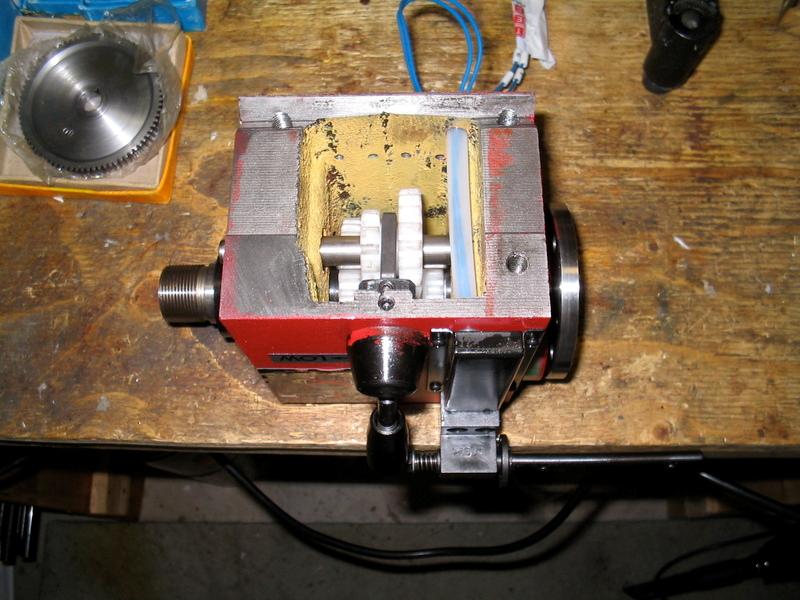
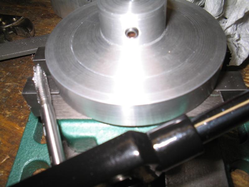
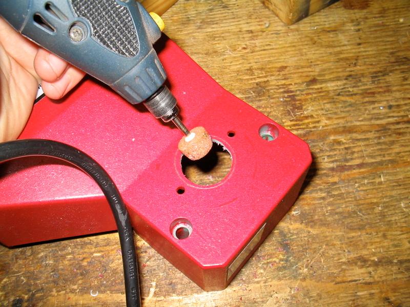
Next I opened up the gear cover/housing for clearance:
(Click PIC to Enlarge)
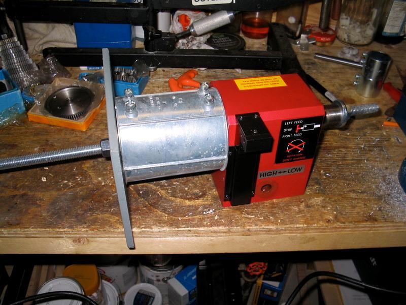
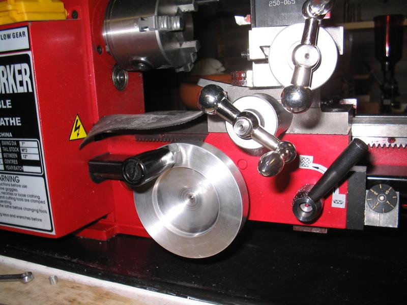
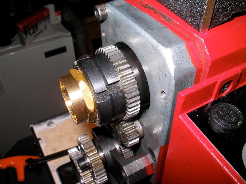
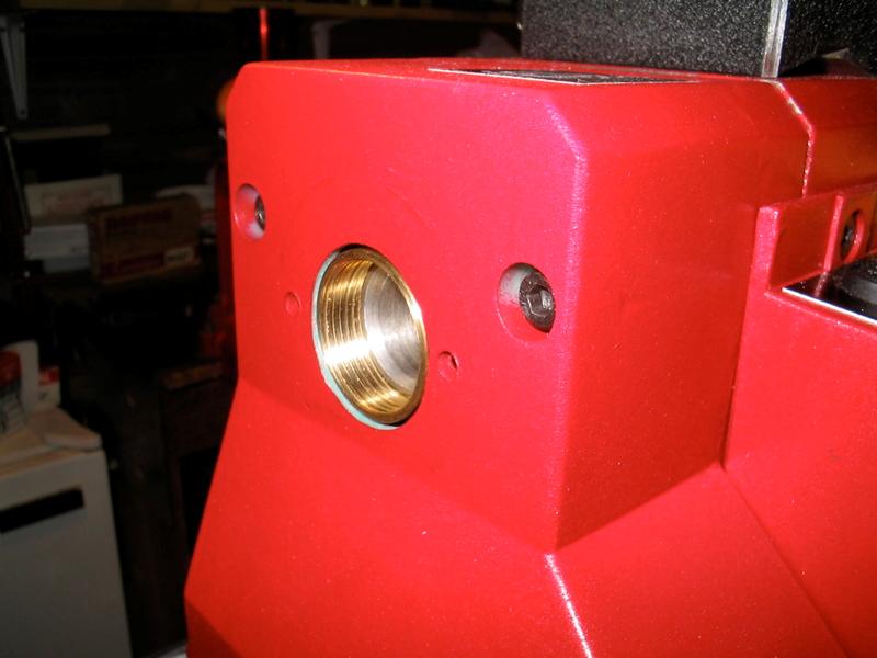
Voila! Extended JUSt enough to drop the chips out the back of the lathe with the gear cover on:
(Click PIC to Enlarge)
I actually left it recessed about 1/32" because I have to account for the indexing disc I'm going to install for the spindle RPM readout modification...
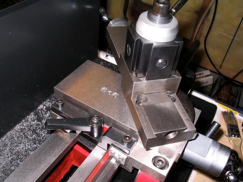
Next up, I decided to eliminate as much saddle slop as I could to really reduce the lathe chatter to insignificant levels. I did this by making tapered saddle gibs. I followed Rick Kruger's design for these - can't take any credit here. (YOU NEED A MILL TO DO THIS MOD)
First you make a taper jig and then start machining the L-brackets. Rick used keystock, but I didn't have any, so I used cold-rolled 1018 mild steel bar.
I used a 3/8 end-mill to cut the bracket tapers. Layout dye is a big help in taking off the .300" clearance.
(Click PIC to Enlarge)
Make sure you make them with the cuts on the opposite side when you machine the second bracket!
(Click PIC to Enlarge)
I cut them to rough length in the chop saw and then squared them off to finished size using end mills.
Next, I located and center-drilled for the M4x0.7 adjusting screws in the mill.
(Click PIC to Enlarge)
Then the holes were drilled to depth in the press:
(Click PIC to Enlarge)
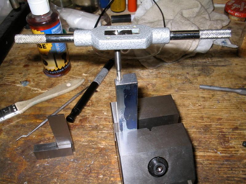
And finally they were tapped using decent USA made taps. I have too much bad luck with the cheap chinese taps I wish I never bought!!!
(Click PIC to Enlarge)
Tip: when tapping long 3/4" blind holes like these, USE CUTTING OIL. It's is NECESSARY unless you like broken taps. And use a decent T-handle if hand-tapping. The crappy collet-type L-holders are junk.Information

Warning: This is a relatively older thread
This discussion is older than 360 days. Some information contained in it may no longer be current.
- Knowledge Library

- MKL Entry of the Month
- Australia
- Austro-Hungarian Empire
- Canada
- Czechoslovakia
- Denmark
- Finland
- France/Belgium
- Germany
- Italy
- Japan
- Norway
- Russia
- South America
- Sweden
- Switzerland
- Turkey
- United Kingdom
- United States
- Yugoslavia
- Is my rifle authentic or a fake?
- Jay Currah's Lee Enfield Web Site
- On-line Service Records (Canada)
- Technical Articles/Research
- Forum
- Classifieds
- What's New?
-
Photo Gallery
- Photo Gallery Options
- Photo Gallery Home
- Search Photo Gallery List
-
Photo Gallery Search
- Video Club
- iTrader


 PM
PM