Note: After you click on images to ENLARGE them, you may find they automatically size smaller in your browser's window making them harder to view. The auto sizing is your browser's way of keeping images entirely within the screen size you have set. Move your mouse pointer to the bottom centre of the pic and you will see an options panel appear. There will be a small square box next to the large X, which will have a pointer arrow sticking out of it. If it's illuminated, it means the pic you're viewing can be enlarged, so click on this box and the pic will EXPAND and open to its normal size.
Making Up a Useable No.4 Sniper
(Part 2 - The front end!)
By Peter Laidler
By now, you should have your centered telescope in its bracket with both drums set to 0. What we’re going to do next is to fit the front pad so that when you tighten up the front thumbscrew, the bracket and therefore the grat will swing up and down EXACTLY across that DAP.
It’s important that you read, re-read and fully digest these simple instructions over a glass of scotch while the wife is out shopping and the kids are out playing……………
Clean off the bodyside where the front pad will seat down to clean white steel while trying to get that part as flat as possible without resorting to a milling machine. You’ll get it pretty flat with careful use of a file….. Now, using some means, such as a suitable adhesive or better still, soft solder the front pad onto its final position on the left hand bodyside. You can now drill the three holes. You can do this a couple of ways to suit your means but I want you to do it this way, so that there is no mistake or room for error.
Using the now fixed front pad as a guide, drill through the three holes with a .1456”/3.7mm sized clearance drill sufficient to make a SHALLOW IMPRESSION into the rifle body. JUST MAKE A CENTRED IMPRESSION/DEPRESSION. DO NOT DRILL THROUGH. Then, using the ‘centre’ that you have marked with the .1456/3.7mm drill, now drill right through the body side with a .118”/3mm 4BA tapping drill. You can carefully tap these holes with the pad in situ.
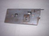
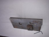
For this exercise I have shown a small steel plate on which the body is securely fixed and ‘squared’. This plate was used at our Base workshops to hold a body securely while drilling out and re-tapping broken pad or other body screws. You probably won’t want anything quite so elaborate but you MUST drill the body square!
A plate made for use at a Base Workshop, to drill out broken/sheared pad screws etc on No4, T, No8 and L42 rifles. Not only that, but to hold bodies for other purposes such as re-engraving too. The large recesses are to allow clearance for the right hand side of the charger bridge and the cut-off block. The allen screw at the top right is to lock down the backsight ear – critical for squareness while the double allen screwed undercut block is to lock down the bodyside.
 (Click PIC to Enlarge)
You can see now that the screw holes in the pad and threaded holes in the body are perfectly aligned. And you can remove and replace the pad at any time, knowing that as they are a matched pair, they will always align. Because, that’s JUST what we’re going to do now. BREAK THE PAD AWAY FROM THE BODY and clean off any adhesive/solder etc etc. Now screw the pad back onto the body tightly.
The body and barrel should be correctly mounted into the fore-end. Don’t bother about the handguards or trigger mechanism/bolt etc etc. Punch out the cap of a boxer primed cartridge case, clean out the hole and insert it into the chamber (with a dob of grease so that it won’t fall out). Now using whatever means you have….. an aiming rest is pretty good, but strapped to a sturdy ladder/workbench etc with cramps/clamps will do - boresight/align the bore onto a DAP 1Km or so away. Fit the bracket and telescope to the front pad and gently move the bracket up and down on its front pad axis and see where the line of the grat point is in relation to the DAP viewed through the bore. For our purposes, I’m going to say that it is way over to the left………………..
If you were pretty stupid, you COULD just screw the grat over to the left and be done with it! But that is a bubba trick* and we are going to do it properly….., by optically aligning the axis of the centered telescope with the true axis of the bore. Where were we……? Ah, yes. The grat is way over to the left. So what we are going to do is to gently file the pad (NOT the rifle body…..) along the screw hole area while taking more off at the front part than the rear. In other words, you will be ever so slightly tapering that mating area. In doing so, you’ll be swinging the telescope and bracket to the RIGHT….., JUST where you want it. It won’t take a lot because the accumulative error ratio over 1Km will mean that pretty soon, as you rotate the telescope/grat up and down, the adjustment to the front of the pad will soon swing the point of the grat to the right - slap bang ON to your DAP.
There it is. The SECOND and most important part of our No4 sniper project. Now we’ve got an optically centered telescope in its bracket, a front pad that is now ‘matched’ to its rifle and best of all, a bracket that screws onto the pad that is collimated exactly to the centerline of the bore. Just how much better than that can it get?
Note: If you have any questions or don’t understand something or my instructions are ambiguous then please ask on the forum and NOT by PM. That way everyone will get the benefit of the question and answer.
Next time, we’ll set up the true optical elevation using a similar but subtly different method with the rear pad. So don’t jump the gun!
* This is also a trick used by those trying to convince you that their 'matched' rifle and telescope is just how it's always been since their uncles brothers auntie got it from the factory..... It's NOT!
Copyright ©2006 - 2010 by Peter Laidler and MILSURPS.COM (Content Policy)
Collector's Comments and Feedback:
1. Capt. Peter Laidler is the senior Armourer in the UK Military, now retired, but based as a Technical Officer at the UK Military Small Arms School. In addition to being a trained and highly experienced military "Armourer", he has authored two excellent books about the No.4(T) sniper rifles and their No.32 scopes. They are titled "An Armourer's Perspective: .303 No.4(T) Sniper Rifle", which he co-authored with Ian Skennerton and his own dedicated work, "Telescope Sighting No.32".
If you're really interested in some in-depth learning about the No.4(T) sniper rifles and the No.32 series of scopes, their history, evolution, repair and adjustments for shooting, I'd highly recommend those two books, which are pictured below. ....... (Feedback by "Badger")
Note: The opinions expressed herein or statements made in this article are solely those of the author, and do not necessarily reflect the views of the Military Surplus Collectors Forums, or the ownership and moderation group of this site. MILSURPS.COM accepts no legal liability or responsibility for any claims made or opinions expressed herein. Also, please note that neither the author nor MILSURPS.COM recommends that any member of these forums, or a reader of this article, try this type of experimentation without the proper knowledge, equipment and training.


 Reply
Reply
 Countries
 Categories