-
Legacy Member

A 10 year holiday compliments of the govt.
Actually there's nothing stopping you doing it, but you could never make it legal.
-
Thank You to gsimmons For This Useful Post:
-
02-07-2014 07:16 AM
# ADS
Friends and Sponsors

-
FREE MEMBER
NO Posting or PM's Allowed

Peter,
Would not have wanted to go to Aden either. Read a few books those exploits..not fun for either side. The insurgency thing is always a long drawn-out affair. I was a bit after your time, having gone to Airborne School in 1980. Never assigned to an A/B unit though, flew helos in the Army and A-10s in the USAFR most of my career.
The tube for the STEN that is approved for use by ATF is same outer diameter, but slightly smaller inner diameter so it will not accept the STEN original bolt. I would essentially have to build two completely different ones to do that, so I will stick with the semi. There are a few Curio and Relic STENS floating around the country, most in collections and they push $11,000 and up. The "tube guns" as you describe typically run $5,000 and up. Too bad the gangsters in the 30's had to mess up the fun for us. The ATF sorta frowns on us having those without papers ya know.
I will be doing my milling with a drill press and x/y adjustable table and clamp kit. I hope to use that set up for other projects in the future. I watched the guys build STENs with a hand drill and dremmel tool, but don't feel I could do it well enough without the stability. Besides, it gave me an excuse to buy a few new tools! 
I am open to any advice from everyone as I progress. I have fully read the post on this forum on building the Canadian version, and that is what drew me here.
-
-
FREE MEMBER
NO Posting or PM's Allowed
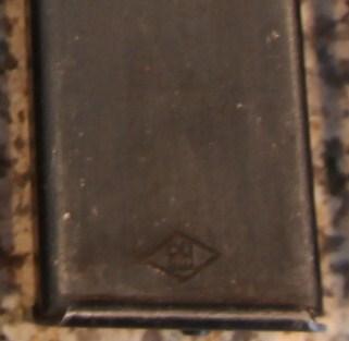
Does anyone know which manufacturer uses this mark in the diamond on the bottom of the STEN Magazine?
-
FREE MEMBER
NO Posting or PM's Allowed
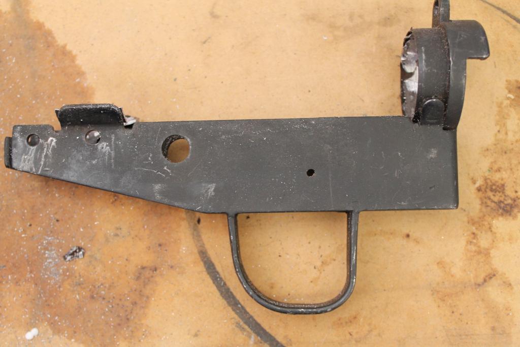
Progress for Today: Removed the torch cut receiver tube from the trigger housing. Since I tend to get impatient and my work suffers, I'll stop at this point and use another day to clean up the trigger group. Here's the round up:
I looked through a few web sites where others were building STEN III or V's. I noticed on one of them, the man damaged the upper rim of the Head Casing when he removed the tube from the back. I suspect he did not fully remove the spot welds and when the tube was bent upward to remove from the Rear Head Casing, it took a chunk of metal with it. I wanted to prevent that, so I proceeded slowly.
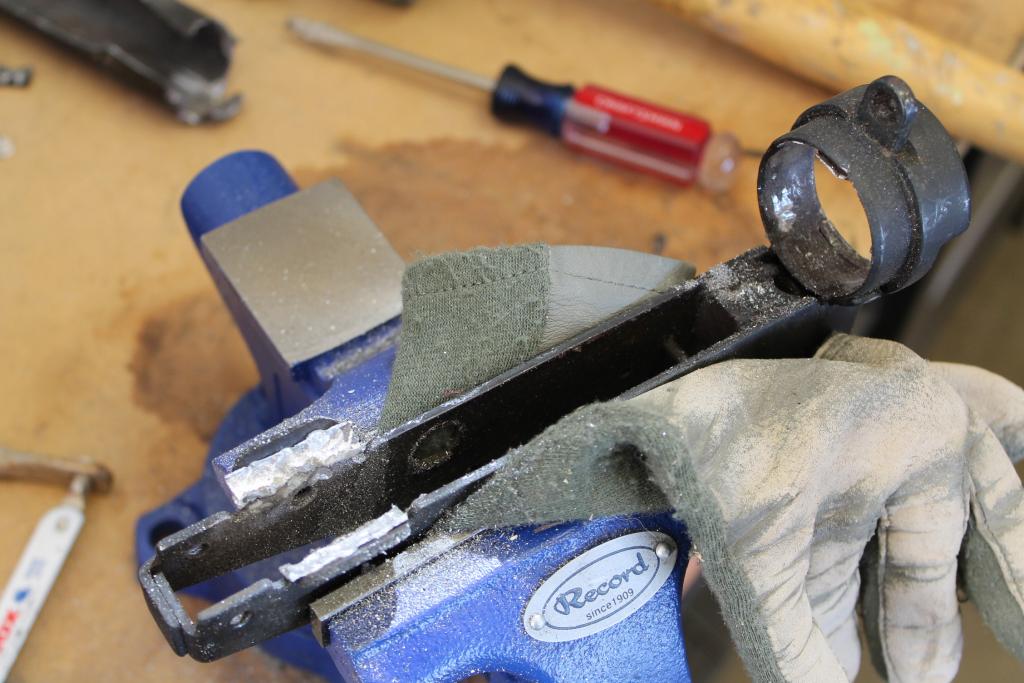
Started by clamping the tube in the vise being careful not to clamp the tabs on the Case, Trigger Mechanism. The spot welds are fairly easy to see, but once the metal glitter flys, they get covered up. I started by marking the welds so I could grid easier.
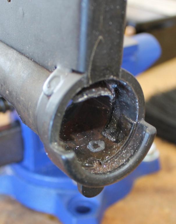
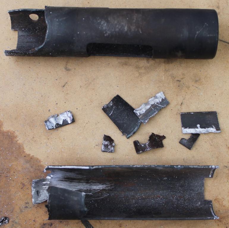
I then began to grind using the TiN metal cutting bits from the Dremmel tool to eat away at the welds. As I made some progress I was able to get a small pry tool between the tube and the Head Casing Ring and pry the tube slowly away. This told me how my progress was going and let me see how deep my grinding was so that I did not cut into the Head Casing. Here you can see the progress as I gind the tube, being careful not to exceed the thickness of the tube and go into the Casing. You can also see the pieces being separated from the casing by light prying and bending.
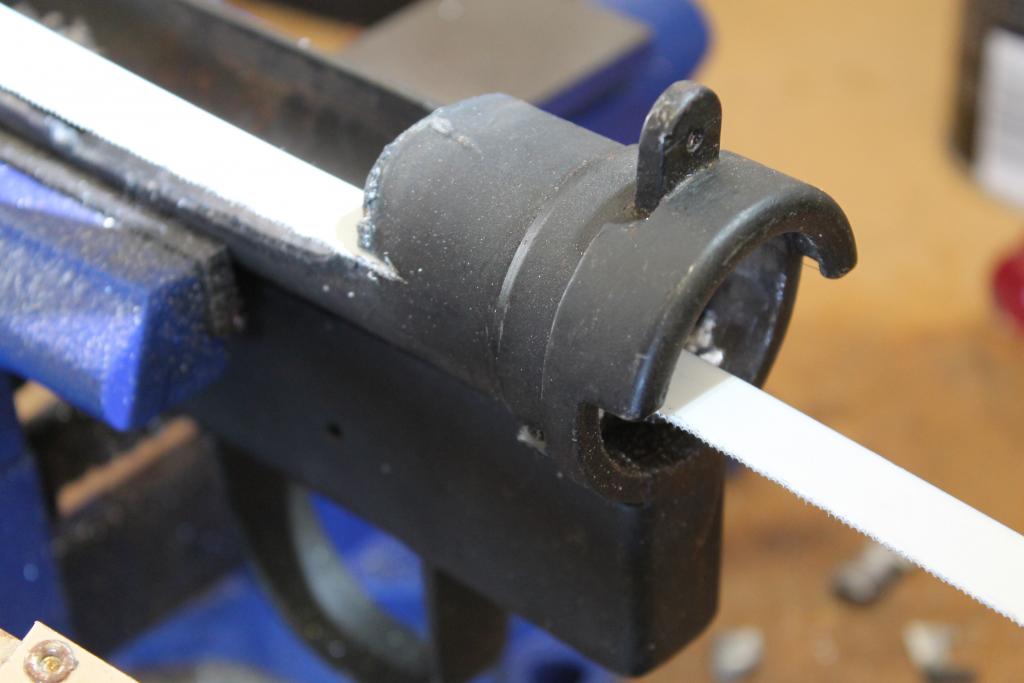
It occurred to me that if I cut the back of the tube, from the weld cut to the back, I could begin to roll up the tube on the inside as I ate away the welds. This allowed me to grind away without goig too deep. In the next photo you can see where I took the hacksaw apart, turned the blade upside down and reconnected it to the hacksaw frame so I could say inside the tube. This worked real nice and I was able to cut through only the tube from the torch cut to the back of the tube.
Here is the progress after the cut was finished and you can see how easy it was to roll the tube inside the Rear Casing. This really helped with the weld removal. Notice how there is no damage to the Casing Head. Success.
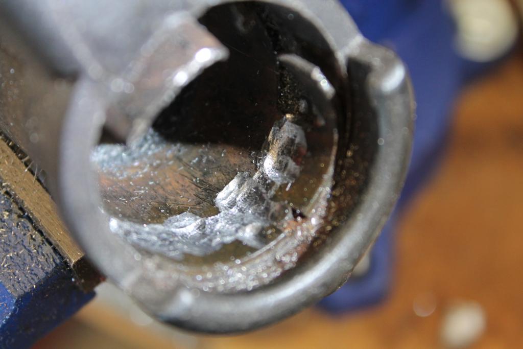
The next step was to clamp the Trigger Case Mechanism using some leather to prevent marring the parts that I want to use. I began grinding with a ball grinder on the Dremmel. I was hoping to use my drill press and Ball Mills to grind away the welds and not damage the two tabs on the housing. As I began to grind the inside of the tube I realized i could cut the tube completely off in front of and behind the two tabs. I failed to photograph this step, but you can see in the next photo where the cuts were made. Just in front and behind the tabs there are small recesses that allow you to cut with a hack saw without touching the housing below. This left a small ring of metal only over the tabs, and as I ground away I was able to bend the tube back and away from the tabs without damaging them.
*****Wait to do this until you get most of the welds removed or you might bend/snap off the tabs.
All I have to do now is clean up the inside of the Rear Head Casing and the inside of the two tabs and the trigger mechanism housing will be ready for blasting. This step did two things for me:
1. Saved $200 by not having to buy a newly made mechanism,
2. Saved all of the valuable marks and Broad Arrows on the housing.
Reusable???
More Later
-
Mmmmmmmm. Thinking out aloud..... it'd be difficult to turn the main casing tube out of the trigger mech/read head casing on a lathe. But you've got it started. I didn't see a barrel in the original photos. Do you have one?
-
-
FREE MEMBER
NO Posting or PM's Allowed
Peter,
I hope I understand your question; with the work I've done here, I will not need to turn out a Rear Head Casing as it is attached to the Trigger Mechanism Housing. I merely need to clean up the inside diameter a bit to accept the receiver tube. The receiver tube that I have in the mail, once properly milled, will fit nicely into the rear in the Head Casing and will lie on the two tabs. I need to clean the excess welded metal from the tabs and return them to their original thickness. As far as i understand I merely need to spot weld the tube onto the tabs and the rear head casing.
Indianapolis Ordnance has the 7 3/4" barrels, newly machined from 4130 steel to the original specifications. I will have to wait for my ATF approval before I can receive the barrel in my possession, as the ATF would consider possession of the components and a short barrel as intent to manufacture an NFA weapon without approval. Despite this warning everywhere, the ATF agent i contacted in my district said he did not care as long as my paperwork was submitted..Hmmmm
-
FREE MEMBER
NO Posting or PM's Allowed
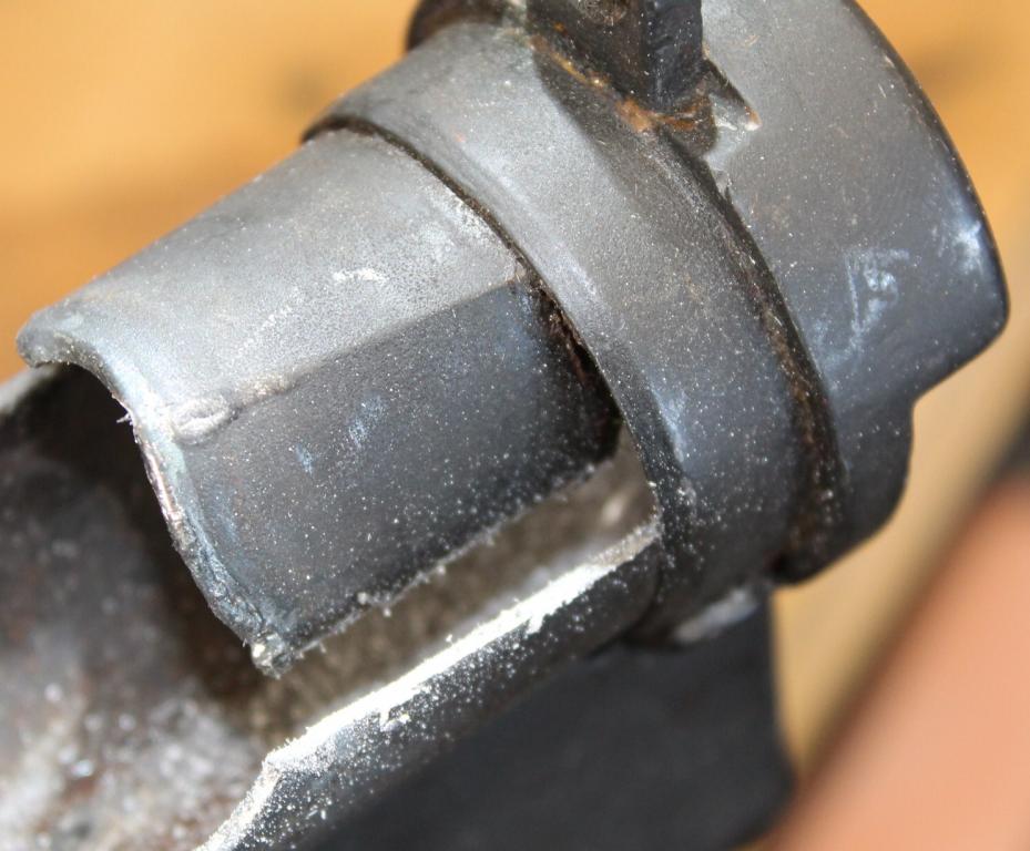
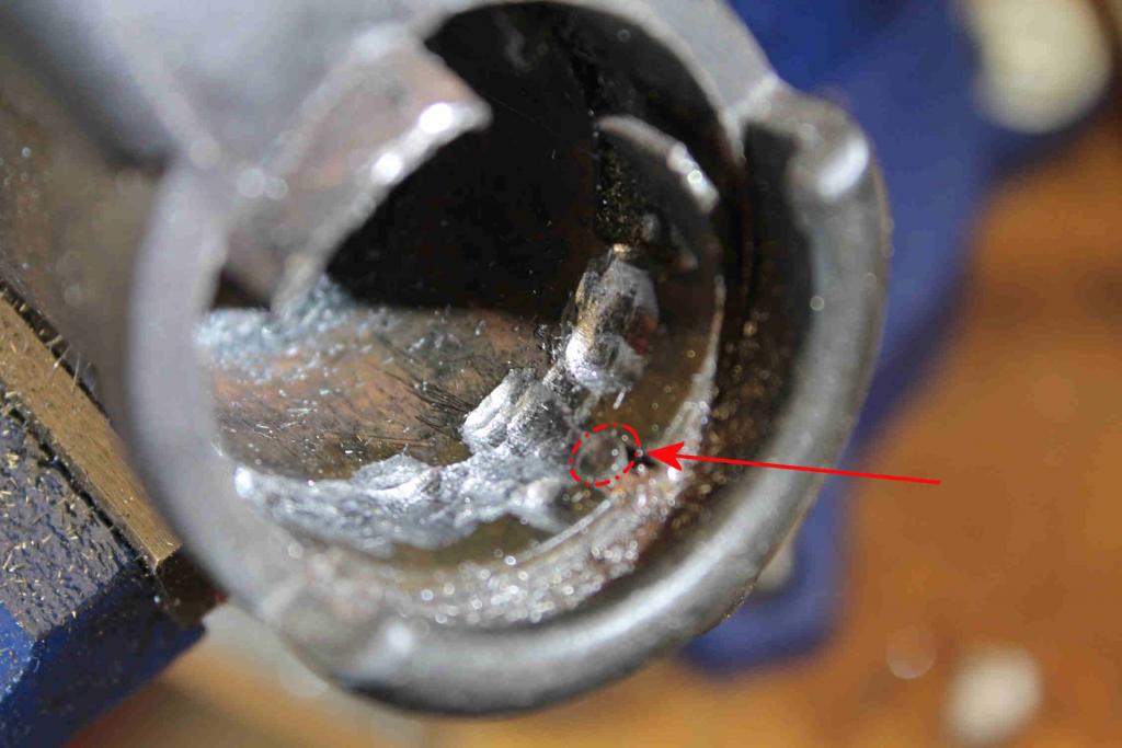
Something I forgot to mention....there is a small pin that protrudes from the inside top of the Rear Head Casing. The pin serves the purpose of accurately positioning the receiver tube to the correct depth and at the correct angle with the trigger mechanism casing.
**** Take care not to grind it off when removing the tube.
-
Are you sure about the purpose of that pin 17th? I seem to remember that the pin was part of the backsight leaf that ensured that it was sat and welded in the correct lateral position on the rear head casing. Maybe it intrudes a bit and serves two purposes. Similar thing on the Sterling SMG's too
Great project............
Last edited by Peter Laidler; 02-10-2014 at 05:44 PM.
-
-
FREE MEMBER
NO Posting or PM's Allowed
Peter,
I'm not totally sure, but in the image you can see where the receiver tube has been notched at the same 12 o'clock position so that it will slide around the pin. Perhaps the dual purpose as you propose is correct. When the tube arrives today, and assuming the template is a 100% match for the Mk V as the company says, then there should be a marking to mill the small slot for the pin as shown in the image. I'll post photos of the tube when it arrives and we can see how I should mill that. In any event, it should serve to position the tube correctly in the head casing so that the mag well and ejection ports are at the 3 and 6 position.
-
Legacy Member

That pin is the base of the rear sight as Peter has said, it also trues up all the parts as the photos I have show the head casing, trigger plates and tube as separate items being jigged and welded at the same time rather than a pre assembled head casing and side plates being welded to the tube. On the Mk2 gun, there is a hole in the tube for this pin rather than a slot as on your Mk5 and as you can imagine, this proves you couldn't fit a pre assembled head casing onto the tube as the pin wouldn't go into the hole.
Also the V changed to a 5 in Oct 1944 I think it was.
-


 PM
PM