-
Legacy Member

Guys,
Unfortunately we are continually chasing our tails on this thread. We can't analyze a semi Bren in the same way as an original FA. Every part of the original was made to spec. The semi is essentially a one-off one of a kind build, even the "professionally" built guns. They do not have totally interchangeable parts.
Even the semi operation can be different. The version that HA builds and Vincent has discussed, has a separate striker spring that cocks on the rearward motion of the bolt and carrier. The version I built has the striker spring on the recoil spring guide and consequently cocks on the return motion of the bolt & carrier. Some were built as hammer fired guns.
I've spent countless hours making adjustments to get mine to run properly. I'm sure the "professional builders" have become much more efficient.
Most of us, as I have said before, could solve the problem if we had the gun in hand for a few days.
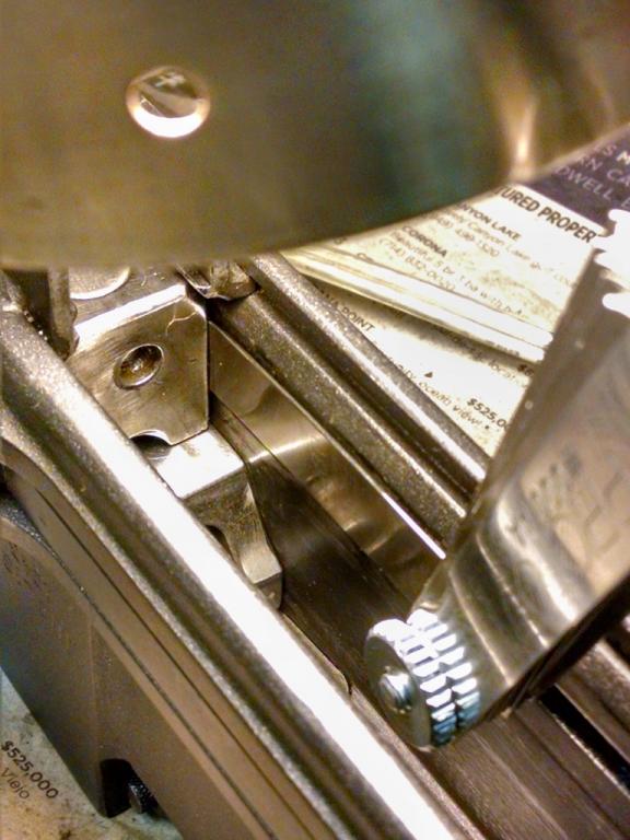
If Djandj had just stoned a little off his LS we wouldn't be having this discussion but it precisely points out what I noted above.
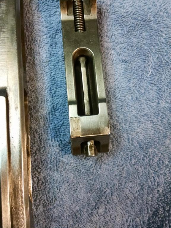
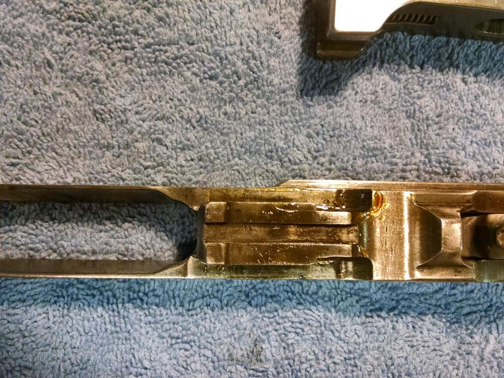
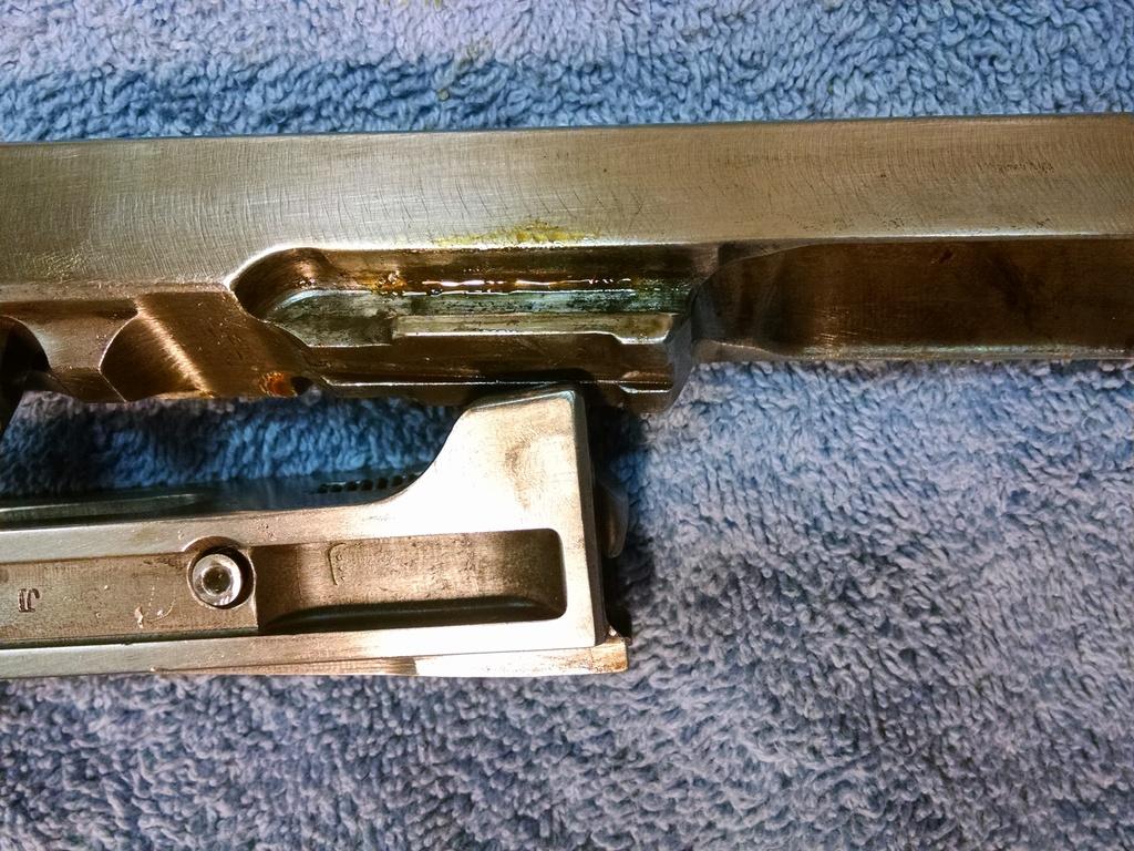
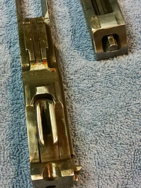
Below you can find what I have regarding Locking Shoulders. The one item is from "The Bren Handbook" and I think all it gives is the thread spec and length range "H" & "L" of the shoulder. The other info is the dimensions of a LS I made and is now in use. I ground off too much and had to make a new one. Only the length is different, all the other dimensions were from the original that came with the gun.
Joe
Attachment 63207Attachment 63208
-
The Following 2 Members Say Thank You to Joe H For This Useful Post:
-
06-03-2015 10:47 AM
# ADS
Friends and Sponsors

-
Legacy Member
Nope...... got a live gun stripped in front of me. This might be different from your semi rebuilds but in the case you illustrate Vince, it'd be the advanced feed horns causing the BB to hang up. Or they might/could foul on the protruding l/sh screw - if it does. If so, then just grind a small chamfer around the threaded end of the screw!
However, I CAN get this feed horns hang-up situation to arise but only artificially.
To make the my point in the previous post. It could be that there was a slight bump in the carrier rail slot (which it only has one of) on weld up and the builder ground the LS channel so the gun would operate.
Just conjecture to illustrate my point
Joe
Last edited by Joe H; 06-03-2015 at 10:59 AM.
-
Thank You to Joe H For This Useful Post:
-
-
Legacy Member

Thank you, Peter. I will chamfer the screw and the back of the locking shoulder channel.
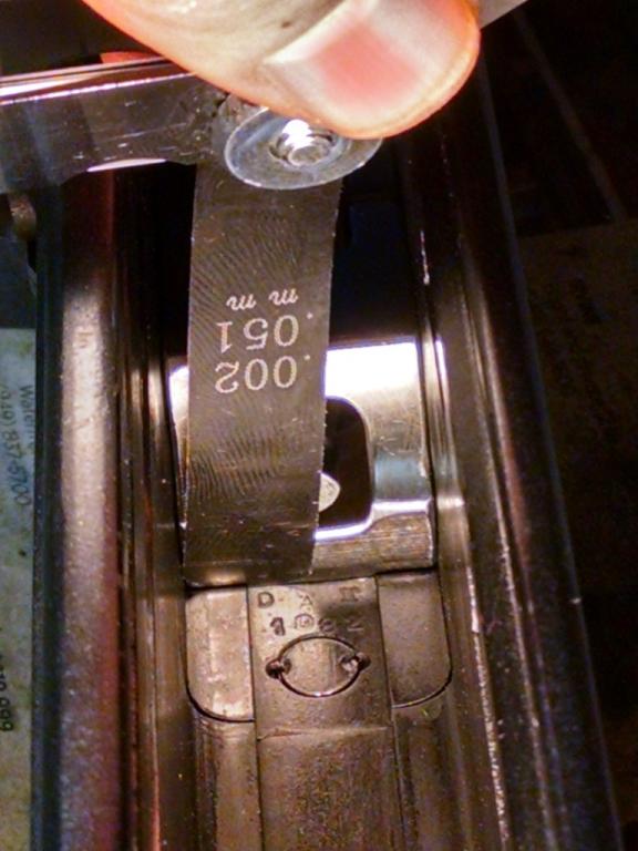
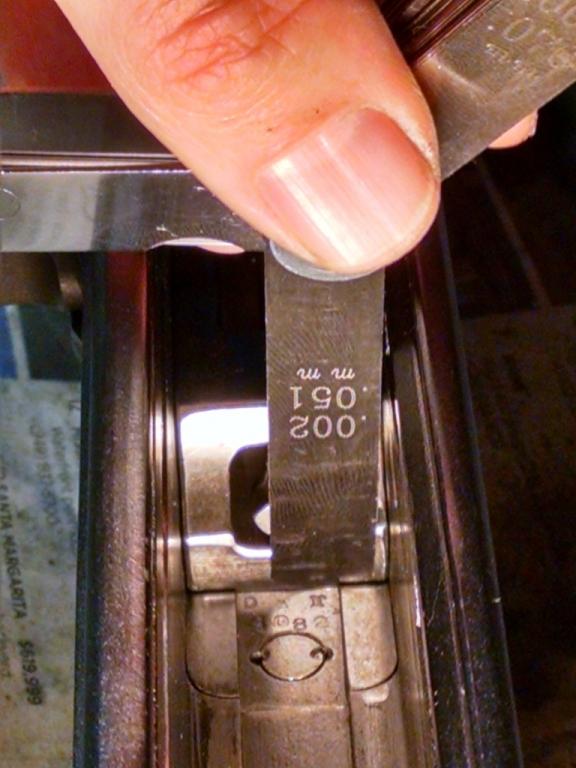
The question is since his shoulder didn't allow for much, if any, room for bolt movement when installed, (still couldn't get the .005 feeler gauge between the bolt and the new shoulder) should he pair back the edge by another .005 while he has it.
What do you think, Peter? Take .005” more off the locking shoulder?
If you still have that Bren stripped, could you put a feeler gauge between the bolt and the shoulder and let us know what you get?
-
-
Legacy Member

Originally Posted by
Joe H

To make the my point in the previous post. It could be that there was a slight bump in the carrier rail slot (which it only has one of) on weld up and the builder ground the LS channel so the gun would operate.
Just conjecture to illustrate my point
Joe
It’s not difficult to machine or grind away a “slight bump in the carrier rail slot.” I can’t see grinding the locking shoulder for that. Now if the receiver sections were not properly aligned in the jig, I can see having to do that. It also explains so much of why this gun was built the way it was. Not how I would have approached it, but ingenious none the less. Who would have thought a Bren would run with only one carrier rail!
-
-
Legacy Member
-
-
I am sup[rised that your US rebuilders don't leave, say a 3" or so length of useable guide rail on the left side of the piston extension, forwards of the cotter that retains the piston post. That together with the same amount of useable guide rain groove in the body. That would definately help support the recirocating BB&P assembly. At the same time, the now short length of un-welded/useable track left in the rear end of the body would prevent the use of a full auto BB&P assembly.
Or is this against the rules
Incidentally, and a little bit off subject but sort of relevant to Bren re-manufacture. We had a little test for the serviceability of the extractor stay and spring; and it's this.
1)BB&PE out of the gun. Put a spent shell case or dummy round onto the breech face held by the extractor and assemble the BB to the PE. With me so far?
2) assemble BB to PE, slide forwards AND THEN REARWARDS .2" so that BB stops at the front of the locking ramp of the PE. At this point, IF the extractor stay and spring are fully serviceable, then the BB WILL spring up and down and stop when it meets with the underside of the P post.
During this, the spent case or dummy will be rock solid on the breech face by the influence of the extractor, ext stay and spring. Clever eh!
Last edited by Peter Laidler; 06-04-2015 at 03:52 AM.
-
Thank You to Peter Laidler For This Useful Post:
-
Legacy Member
I am sup[rised that your US rebuilders don't leave, say a 3" or so length of useable guide rail on the left side of the piston extension, forwards of the cotter that retains the piston post. That together with the same amount of useable guide rain groove in the body. That would definately help support the recirocating BB&P assembly. At the same time, the now short length of un-welded/useable track left in the rear end of the body would prevent the use of a full auto BB&P assembly.
Or is this against the rules
It’s not against the rules. Most are done exactly as you describe, Peter.
This goes way beyond what WAS necessary for compliance. It saves time and more importantly doesn’t require the body sections to welded in close to perfect alignment. The sections can be a few hundred thou off because the carrier can rock slightly and the length of the remaining rail is shorter. The replacement piston also doesn’t have the two rings near the center.
Last edited by Vincent; 06-04-2015 at 01:26 PM.
-
Thank You to Vincent For This Useful Post:
-
Legacy Member
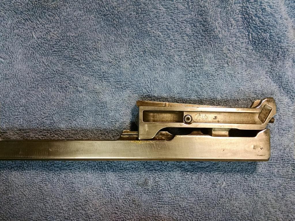
Attachment 63227
Thanks, Joe. That's very helpful.
-
-
Legacy Member
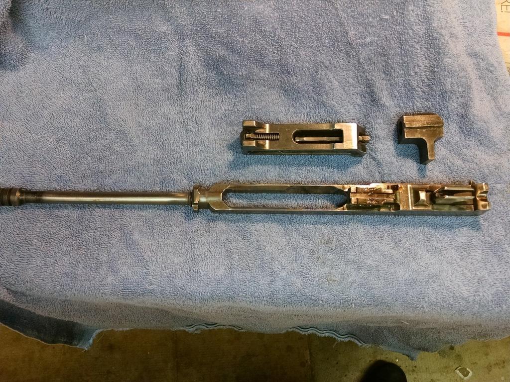
Great pictures, djandj. Are the last two taken with a cartridge in the chamber or an empty chamber?
************
You posted this in post 104:
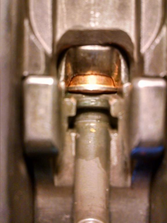
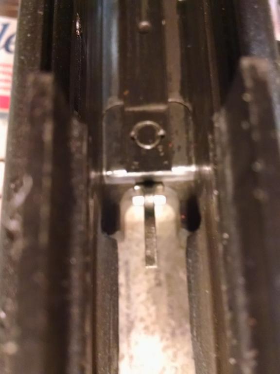
Here we see that even with the cartridge, the spaces between the barrel and the bolt face etc. don't change. The casing fits in the pocket created by the stops and bolt face.
I think a couple of thinks need to be done. First, the cartridge needs to contact the bolt face inside the pocket. There must be a gap between the bolt stops and the receiver when there’s a round in the chamber. Without that we can’t set the headspace.
The pocket on my bolt is .057” deep. How deep is the pocket on your bolt? I couldn’t find it if you have already posted it.
Try the barrel when it arrives. If the round does not touch the bolt face and create a gap by the stops, we will have to look at moving the barrel into the receiver or taking a little off the bolt stops as Joe suggested in post 119. Let’s see what the barrel does first.
Second, Once we have a round contacting the bolt face inside the pocket, we can set the headspace with the correct length (and height) locking shoulder.
In post 131 Mr E said”
Originally Posted by
Mr E
went and measured my spares
786
803
822
I think that once the bolt is moved back off the stops, we might be close to the .803” shoulder he has. It might be worth a try. If it’s too short, we can measure the gap and know exactly what length the shoulder needs to be.
Anyone see anything wrong with this approach? Any other ideas?
Last edited by Vincent; 06-04-2015 at 05:15 PM.
-
-
Legacy Member
Thanks Vince. The pics above are w/o a shell in the chamber. However, as I indicated before, my bolt does not come to rest on the back of the round, but rather the front stops. A pocket as you see is created by the cut outs in the barrel and the bold face. the back side spacing doesn't change whether there is a round in there or not since the bolt stops are dead even with the end of the barrel thus appearing to create a fixed sized pocket for the round. As I said, there is NO movement in the bolt either forward or back once locked down on the shoulder so there is no variability there. The back of the round does contact the bolt face (and is held in by the extractor). For what it's worth, the builder got the tolerances VERY tight with NO bolt movement and no room for the round to move up or back either. I will put your barrel in with are shell in the chamber and get pics and measurements for you.
Thanks again.
-


 PM
PM