-
Legacy Member

I bet you could make a trepanning tool that would work.
Or modify a small woodworking circle cutter.
Attachment 60869
General Tools and Instruments
-
-
03-08-2015 12:55 PM
# ADS
Friends and Sponsors

-
Legacy Member

Hi all, apologies for the delayed reply - have had a hell of a lot of other commitments lately, hopefully I can get some machine time soon.
I think I'd be most confident of the resulting spigot being within tolerance using the radial milling/ dividing head solution as per Peters suggestion, it'll certainly handle the wholesale material removal better than any specialty boring bar I can grind up (its effectively an interrupted cut and body of bar itself would need to be less than .115" - absolutely miniscule)
Using the dividing head is not without problems of its own though @ the set up stage. Its got plenty of angular adjustment however this can only be used to bring the spindle axis into parallelism, to use any of this inbuilt correction to plumb up the No4 action etc would cause it to turn the spigot conically (if only minutely) and be a PITA for the subsequent machining of the rear pad.
Put plainly this means what ever fixture I devise to hold the action for machining, will require (angular/planar) adjustment of its own independent of the faceplate & dividing head it sits on.
Also to allow the dividing head & action through 360* of rotation, The barrel would need to be pulled off so the assembly clears the column of the milling machine.
Does anyone have any specific objection to using an action mandrel to indicate off for the purposes of collimation?
This may be blasphemy/heracy etc, but having the barrelled action setup between centres and expecting every quasi important point between to fall on that imaginary centreline isn't ideal to my way of thinking.
The barrel would likely be replaced in the future anyway @ which point the receiver ring would be faced, threads trued and barrel blank set up to suit the bolt axis, so surely this would be the logical reference to set the bracket pads to and collimate the optical axis to?
flame away 
Also those of you who've made & used the "hold down" plates for No#4 action work, do you find the act of judiciously "dogging" a receiver down causes noticeable distortion/deflection?
Last edited by BrianLara400*; 03-18-2015 at 06:03 AM.
-
-
-
Why dont you drill the spiggot hole then remove the pad, indicate the hole and machine the shoulder with the pad alone on the rotary table?
The rear pad if its a tiny bit big can be machined or filed and scraped to affect collimation. Sorry if youre miles ahead of this...
I have not noticed any meaningful deflection of the body held down in a jig.
Last edited by tbonesmith; 03-18-2015 at 07:35 AM.
-
Thank You to tbonesmith For This Useful Post:
-
Legacy Member
Latest update:
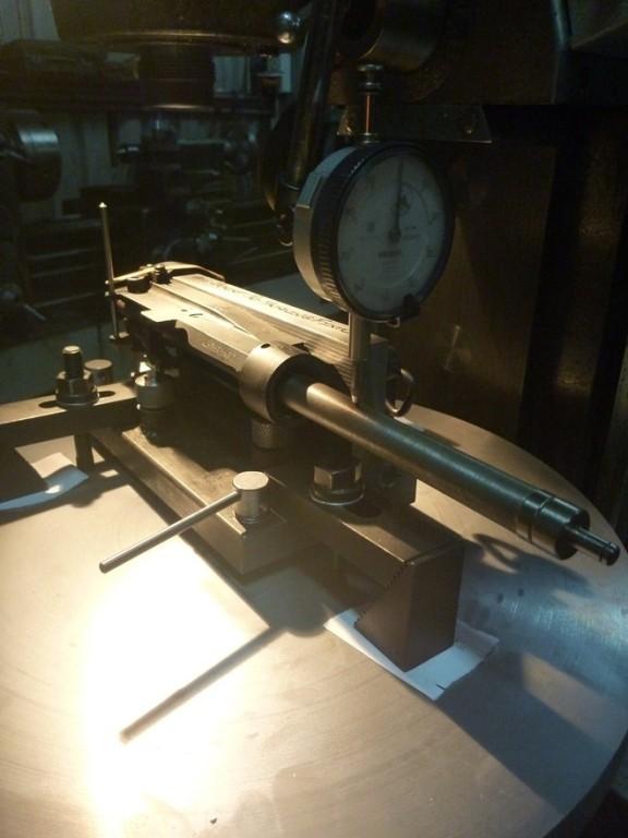
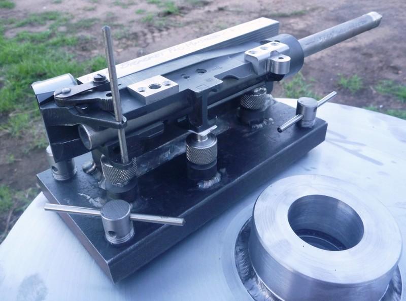
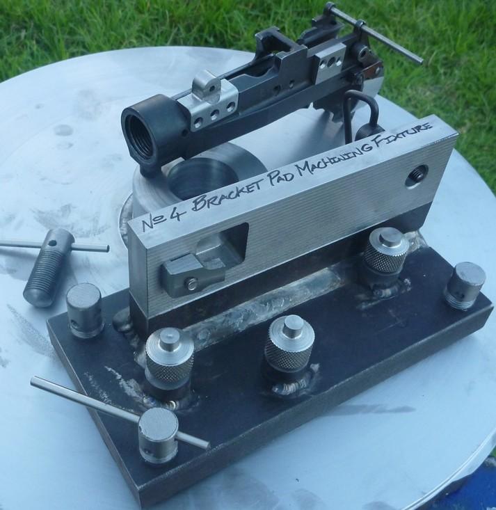
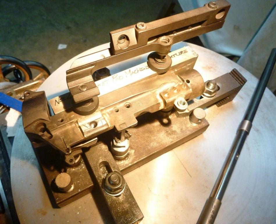
Have finished the fixture to hold the action, as the pads are installed and the interfaces for the telescope bracket are machined.
Its bit of my own variation on the other fixtures I'd seen on the forum - should be plenty rigid & finely adjustable for collimation.
Will work with either the "plunged shell mill" method of forming the spigot or the radial method (though bringing the whole thing into line with the dividing head spindle axis, will no doubt be "fiddly").
- the levelling feet will allow the bolt way centreline & rear sight pin axis to be plumbed up, and the fixture is in turn dogged down to the faceplate.
- the jacking screws bare against the side directly resisting the thrust forces of the drilling/milling operations and in combination with the securing points on the vertical face contribute to the overall rigidity of the work piece. the mandrel itself just rests in place and is a very neat slip fit in the ways
- The faceplate is underway, its been flame cut from 25mm PL x ~400 Dia (rougly as large as I could swing without removing the gap bed - should clear the column of the milling machine by 30mm). Tigg'ed an ASAB bar boss on to it, now just have to go and skim it all true and thread it M45x3.0 to accept the dividing head spindle. - the whole thing should be a "goer" after this and I can get on with the actual project itself rather than all the ancillaries.
Last edited by BrianLara400*; 04-23-2015 at 07:20 AM.
-
The Following 3 Members Say Thank You to BrianLara400* For This Useful Post:
-
Legacy Member
-
The Following 4 Members Say Thank You to BrianLara400* For This Useful Post:
-
-
-
Legacy Member
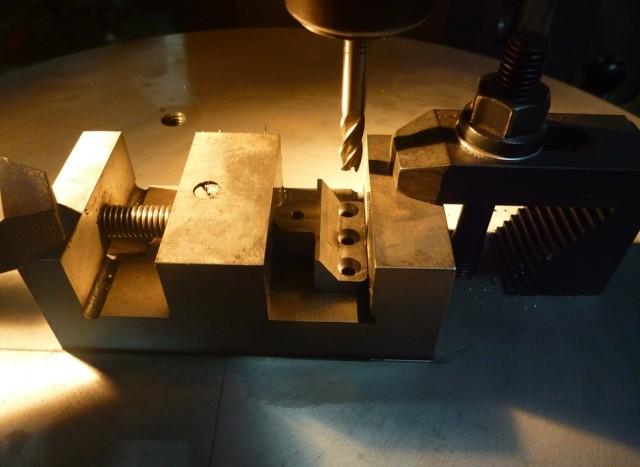
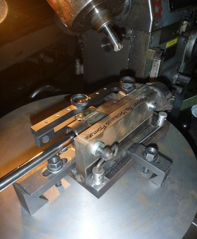
Soldered the pads onto the action and then set about machining the interfaces onto them insitu. Machined the front spigot in radial fashion using a 3/32" end mill (the largest I had to hand, that would pass within the narrow 0.115" constraints.
Then rotated the bolt/mandrel to be parallel to the mills y-axis and tipped the machines head over @ 45 ̊ . Re-establishing a useable/ repeatable reference point proved difficult with the head cranked over, so cut the bevels on the rear pad a little bit at a time, down to finished depth. This allowed the bracket to be trial fitted through out, to test its parallelism in the elevation plane - any fine corrections were then effected my minutely shifting the position of the bevels a calculated distance in the x-axis.
Once machining was complete sweeping along the top (elevation) and sides (windage) of the bracket with an indicator shows no movement of the needle (except for that commensurate with surface texture). An IWS mount was used for the setup, meaning it had a lot of convenient surfaces for the dial indicator to act upon - the lack of the rings did however make it harder to calculate the optical axis' vertical alignment over the action centre-line (was however found to be "spot on" in the end).
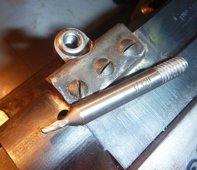
Front bracket pad after tapping & machining of spigot. the 3/32" dia bit is at the bottom end of my comfort zone, as my geared head mill has a relatively low max spindle speed.
(small bites and snails pace rotation of the dividing head)
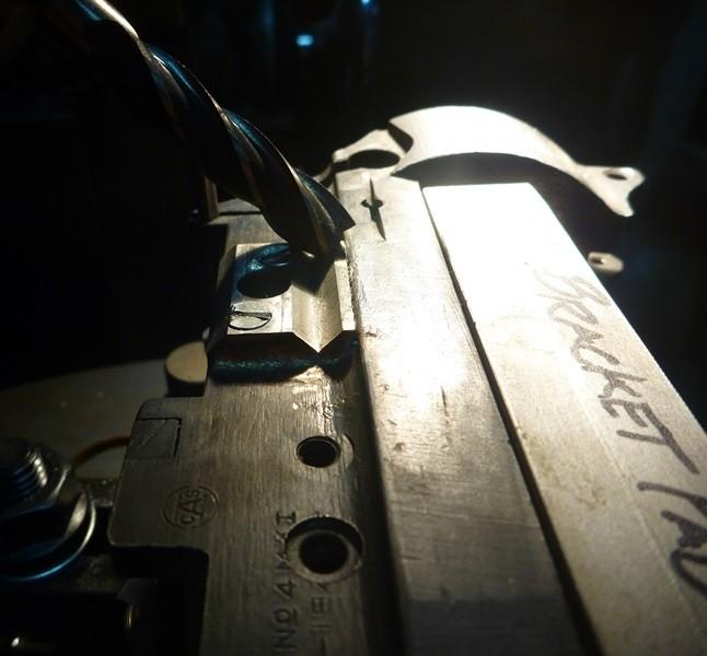
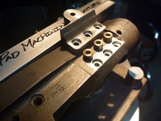
Bevels on the rear pad @ finished depth (the bolt heads were later flushed off using a 45 ̊ cutter).
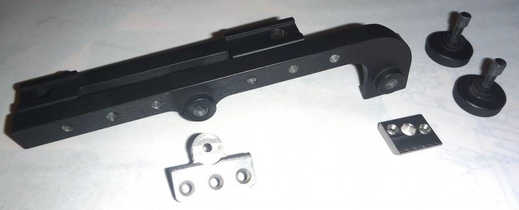
Mating faces on the pads & IWS bracket compared.
Bracket installed and tested, confirmed parallel in elevation & windage plane, and vertically aligned over action CL.
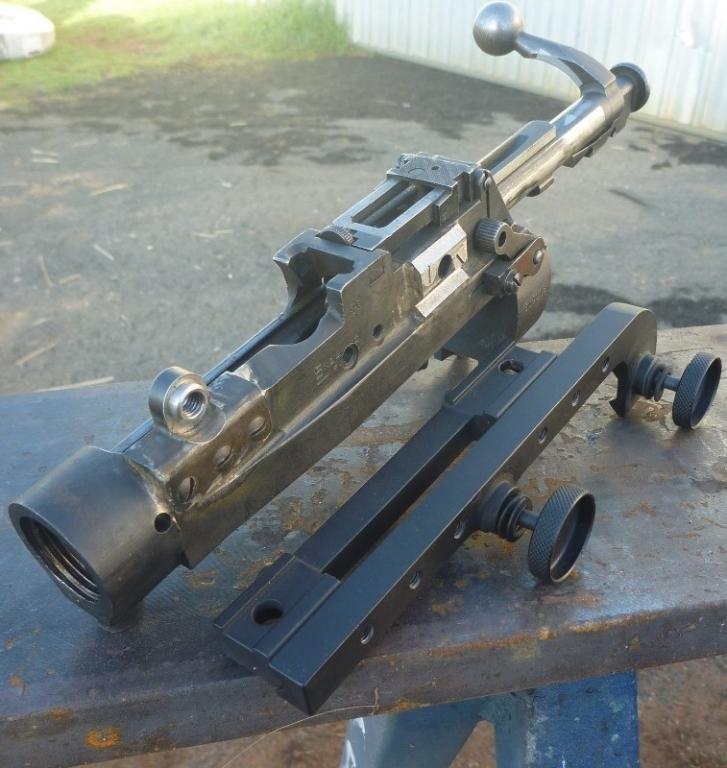
the involved part of the process is now over, now need to do some de-burring, tidying up, re-finishing etc.
As yet am undecided on optics for the project:
*the genuine L1a1 sights are terrifically expensive when they eventually come up for sale and likely needing overhaul),
*don't like the "lucky dip" quality of the chinese repro's No32's, and am yet to see a MkIII or L1a1 version with the "in-line" turrets offered. Would however be open to one of those that Warren had worked on, and then I'd likely need machine some new 762 graduated range drums.
*Would like to go the 6x42 route - I know people vehemently dispute the L13a1/L42a1 combination ever existed except for in the fertile mind of a certain author - but in likelihood would possibly best suit my application i.e mixture of some target shooting, some walk around hunting and spotlighting from a vehicle. The [unicorn] rare extended "trials" bracket might prove the problem in this instance though.
Anyone got a decently tidy S&B L13a1, Kahles ZF84 or ZFM (i.e 6x42 with 26mm tube dia) tucked away they might consider selling?
Post script
*Took the opportunity while the action was still mounted in the fixture to test the brackets "return to zero" characteristics. Setup an indicator on the furthest point forward (cantilevered) on the top & side of the IWS bracket, (the point I reasoned most likely to display variance if there were to be any found) and proceeded to remove and reattach the bracket using different tightening sequences and very lightly influencing it sideways to try and hamper the mating faces reseating.
-Every time I reached final torque, the indicator read Zero +/- nothing-
I'd take this to mean the design of the interacting faces was a very good one, and that any of the original brackets or the likes of Dr Paynes or Surpmils faithful repro's should behave similarly (though wouldn't extend this to the cheaper Asian made repro's - not necessarily machined & toleranced per the DOD drawings).
*The hardened bushings when de-burred and inserted between the action and pads, were of such a fit that there was no discernible movement of the pad when twisting/sliding forces were applied (remembering cheese head bolts & solder were yet to be applied @ that stage). Surely this has to make a significant difference to the longevity of the joint?
*The next time I do a bracket install will likely use the shell mill method, even if it means making one that turns oversize on the I.D. which would allow the last 10 or 15 thou to be skimmed off the spigot OD with the boring head. Will ultimately save a hell of a lot of time trying to bring the fixture & pad onto the same 0,0 axis as the dividing head and get away from using very small end mills with limited spindle speed. May even try using the milling machines overarm to cut the bevels on the rear pad, which would save disturbing the vertical heads alignment (any way, all are things to be considered).
Last edited by BrianLara400*; 05-12-2015 at 06:15 AM.
-
The Following 3 Members Say Thank You to BrianLara400* For This Useful Post:
-
Advisory Panel


Very nice work, very interesting watching this come together.
-
-
FREE MEMBER
NO Posting or PM's Allowed
Very nice work.
May have a scope that will help. Will contact you.
Regards
Mark
-
Legacy Member
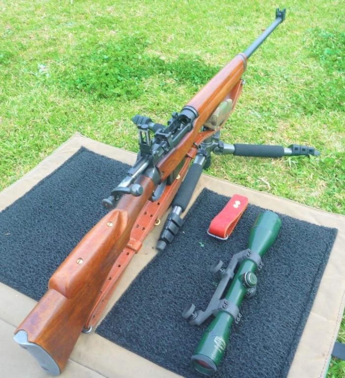
Pretty much finished :)
I had forgotten all about this thread until my memory was prompted by a forumers PM, enquiring on barrel specs. So here are some pics of the final form, this project took on: 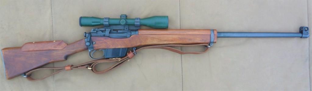
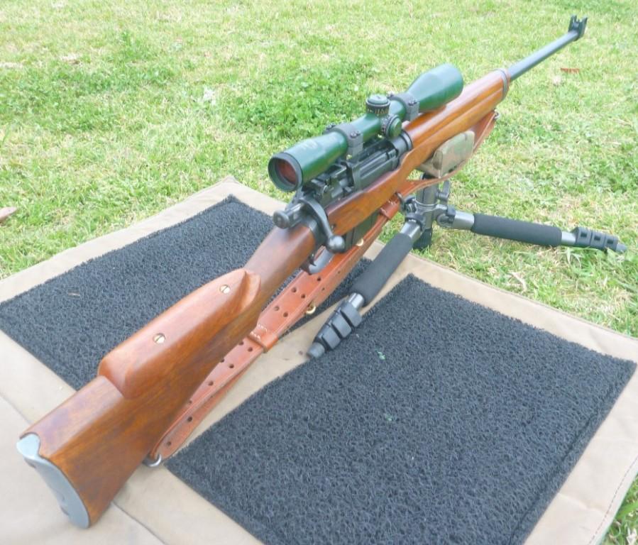
The 1907 sling I pirated from another rifle of mine, was too short for my preferred configuration when prone shooting (long limbs) - this neccesitated a short extension for the forward sling half. (see pictured above ^^^^)
Sourced a L13a1 PM6x42 & repro bracket for this project out of the UK .
.
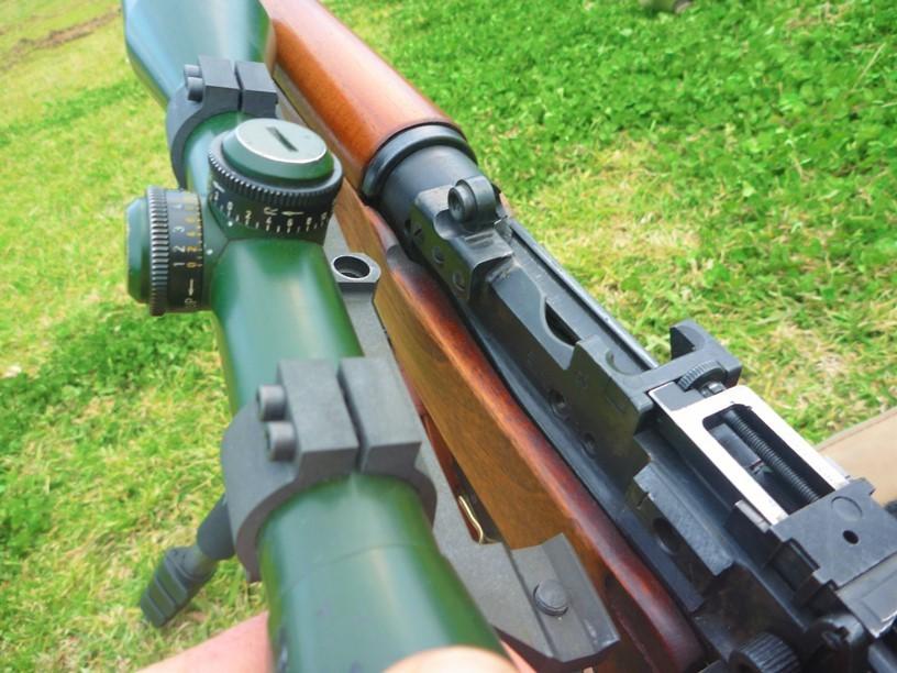
The rifles handguard was probably at the fattest end of savage wartime factory tolerances and wouldn't clear the S&B's larger objective bell, so I judiciously spoke-shaved the height down (evenly) and then blended it with a sheet sander.
Of the photos I've seen of this combination mounted on the L42 i.e in some of Skennerton's publications etc some of those 6x42s look to be mounted impossibly low too, so I imagine that depending upon which individual handguard/top wood was fitted this would often have been encountered.
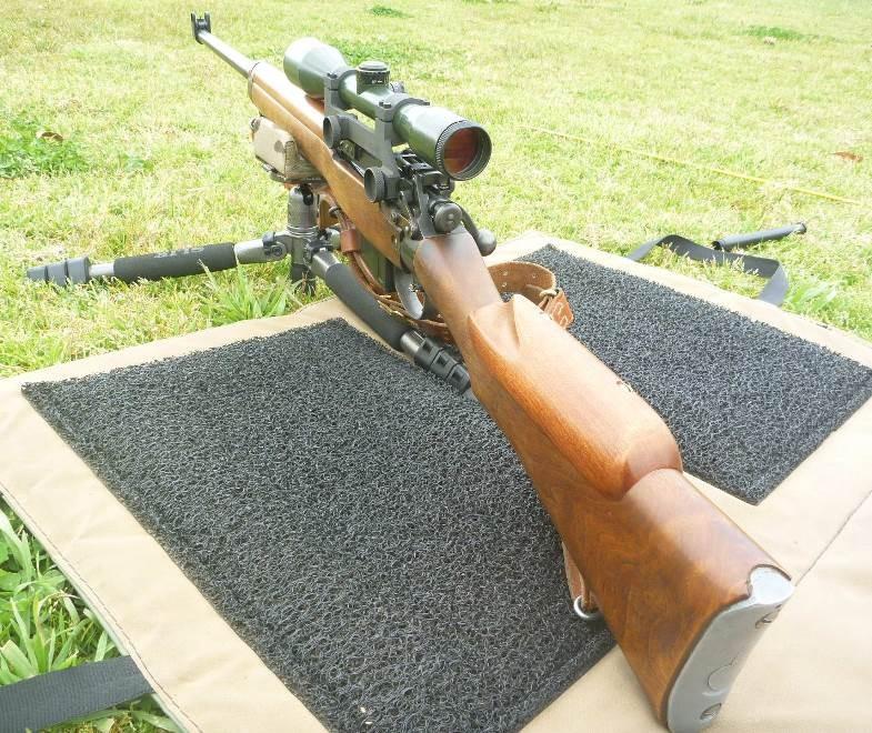
The sportco rifle was very well bedded/ fettled, with brass draws etc when I got it and I've since added some brass/ cork shimming etc in a few critical areas to further improve the wood/metal bedding. I think I can further improve the grouping/bedding a bit without resorting to epoxy/ glass, so will keep playing. Due to the way they assemble/ "stock up" epoxy bedding an enfield action is "involved" to say the least. The 2nd stage of the trigger on my donor rifle, was absolute perfection and probably the nicest I’ve used – but after the tiny bit of judicious shimming etc done to tighten up the critical recoil bearing surfaces in the foreend, the trigger let off did discernably change – not terribly so, still very very good by any measure but it did come back abit from the lofty heights it had been @ before. So the fore-end fit of a Mk1 does have an affect.
The chiseled inlet for the central sight plate on rh side is still evident, from its previous life as a range rifle - though can be blended in at some point down the track if I decide to refinish the fore-end. I stained/re-stained the hand guard & cheek piece to roughly match the existing wood work. Sealed those bits with a handful of coats of 80% tru-oil, 20% burnishing oil.
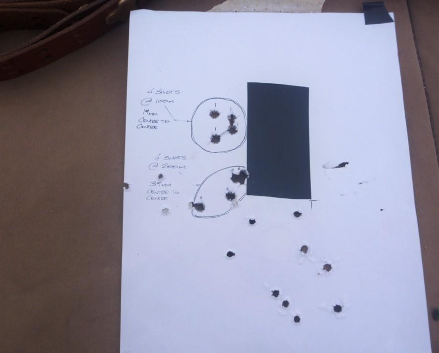
I re-used an old facing, Ignore all the additional holes - they're a different calibre anyway.
I think it's showing a lot of potential so far @ around that 3/4 Moa mark - and it scored quite well in a few positional shooting comps I went in late last year (plus there's been been some feral goats, foxes & pigs who've thought "none too much, of it" .)
Have followed the specs of the original L42 rifles as close as I can within the confines of the donor rifle, i.e
-it already had an additional ejector drilled & tapped into it (which both are redundant - when an RSAF enfield 762 mag is fitted),
-I think the sportco barrel is shy about an inch of length compared to those Enfield hammer forged originals, though whilst there's as much life/performance left in this one I'm reticent to do anything about that
the odd little thing to touch up/ finish off, but overall I think its come up rather well
Last edited by BrianLara400*; 04-30-2016 at 01:24 AM.
-
The Following 10 Members Say Thank You to BrianLara400* For This Useful Post:


 PM
PM