-
FREE MEMBER
NO Posting or PM's Allowed

Last edited by Badger; 12-12-2009 at 03:20 PM.
Reason: Fixed pic alignment for poster ...
-
11-22-2009 05:21 PM
# ADS
Friends and Sponsors

-
It looks like the sight off a Carl Gustav 84mm anti-tank gun. You know, the recoilless thinggy that blows your ears inside out when you fire it!
One thing that does puzzle me Patper is how the rifle can be a Mk1/2 AND be fitted with a Mk1 fore-end?
Mk1 fore-end on a Mk1 type, yes
Mk2 fore-end on a Mk1 AND 2 type, yes
but
Mk1 fore-end on a Mk1/2 and 2 type, NO, it cannot fit!
Last edited by Peter Laidler; 11-22-2009 at 05:30 PM.
-
Thank You to Peter Laidler For This Useful Post:
-
-
FREE MEMBER
NO Posting or PM's Allowed
marking
Thank you for your help Mr Laidler .
.
These photos are the only one I have. I don't see the rifle, and I don't even know how it is fitted.
What do the markings on the right side mean?
What about the bracket?
Last edited by patper14; 11-22-2009 at 06:08 PM.
-
Legacy Member
It's been overhauled by the Indian ordnance establishment.
The sights have become reasonably common on the US surplus market in recent times. The bracket appears to be of the No.32 type.
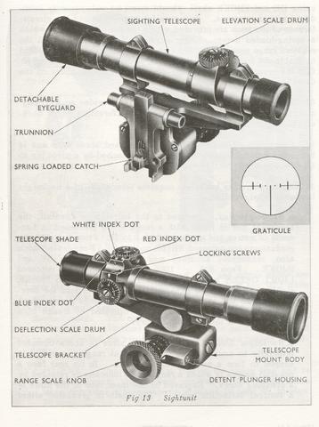
No. 78 Mk.1 Sighting Telescope. The telescope is fitted with two scale drums which are used to bring the line of sight into alignment with the bore of the gun when zeroing. Rotation of the upper (elevation) drum results in vertical movement of the graticule, whilst rotation of the side (deflection) drum results in horizontal movement of the graticule. On the face of each drum is 11 scale graduated in mils, up to 15 mils each side of zero, each five mils being numbered. Engraved on the deflection drum are the letters R and L, together with arrows pointing to zero, to indicate direction of rotation of the drum when correcting the MPI in the horizontal plane. On the elevation drum direction of movement of the drum, when correcting for height of MPI, is indicated by plus and minus signs and the scale is read against index lines which are colour coded as follows:
a. White. The centre index line terminates in a white dot and is used to zero the scale when operating in temperatures of from minus 10 degs. C. to plus 30 degs. C.
b. Red. The rear index line terminates in a red dot and is to be used in temperatures above 30 degs. C.
c. Blue. The front index line terminates in a blue dot and is to be used in temperatures below minus 10 degs. C.
After adjustment the drums are secured by locking screws.
28. The optical arrangement of the telescope comprises a series of lenses which produce an erect image, as viewed from the eyepiece, with a magnification of two diameters and a field view of approximately 302 mils.
29. The graticule pattern is as shown in Fig 13. The pointer represents zero elevation and zero deflection and is used for sight setting. The lead marks represent aim off relevant to speed of target, those to the right of the pointer being used for targets crossing from right to left (see Aiming Chart. Annex A). For targets crossing from left to right, lead marks to the left of the pointer must be used.
30. Telescope Bracket. The telescope bracket is formed with two clamps, in which the telescope is secured and is geared to the range drum spindle thus providing means of adjusting the telescope to any required range.
31. Telescope Mount Body. The mount body houses the gearing through which the range scale knob spindle is connected to the telescope bracket and, on its back face, is fitted with trunnions and a spring loaded catch for attachment to the sight unit mount on the gun barrel. The range scale knob is formed with a knurled head and is engraved with two sets of figures representing range in hundreds of metres. The left hand figures, from zero to 6 in divisions of 50 metres, are used for anti -tank operations; they are coloured white and are for use when firing HEAT shell:- The right hand set, from zero to 13, are coloured LIGHT GREEN and are for use when using HE and SMOKE shell, should these be subsequently introduced into the service [I doubt that they ever were]. Two parallel grooves around the circumference of the knob are provided with a number of dimples in which a spring-loaded detent plunger engages to lock the knob: at the required range setting. At the zero end the grooves are connected to enable the knob to be moved inward or outward on its spindle so that the required range scale may be read against an index on the detent plunger housing.
-
The Following 2 Members Say Thank You to Mk VII For This Useful Post:
-
Legacy Member
I have an Indian No4 MkI/3 T. It differs slightly from most T rifles. From what I can pick up from different sources, the Indians did what they could to keep the rifles functional. If that rifle is a real issue model, it wouldn't surprise me one bit. Compared to mine, it's in very decent condition.
PL is right though, how did they get the tie bar through the trigger base mount?
-
-
Legacy Member

The scope bracket looks to be one of the recently made reproductions. If the rifle really has a Mk.2 trigger setup I'd have to guess that Bubba sawed through the wood, the strap and the pin to make the forend fit.
-
-
I'm with Steve H., here. Looks like a Sarco bracket, possibly. Could someone have knocked out the trigger attach point from the receiver and used an early style trigger guard assembly?
-
-
FREE MEMBER
NO Posting or PM's Allowed
patper14, Because it's a Mk.1/2 (tie plate must be cut) it's either a BSA-Shirley or a Maltby, most likely a BSA-Shirley. (There were a very few Savage Mk.I conversions, but possibly.) Ask your friend to look for circular inspection stamps, if any they're unique to Maltby. The stamping on the RHS of the butt socket:
F.R. Factory Repair
year of repair
R.F.I. Rifle Factory Ishapore
I possibly recall incorrectly, but weren't the SARCO mounts sourced from India?
Brad
Last edited by bradtx; 11-23-2009 at 09:27 AM.
-
-


 Register To Reply