+ Reply to Thread
Page 9 of 22 FirstFirst ... 7 8 9 10 11 19 ... LastLast
Results 81 to 90 of 212

Thread: Starting a STEN Mk V SBR in the US

Click here to increase the font size Click here to reduce the font size
  1. #81
    Advisory Panel browningautorifle's Avatar
    Join Date
    Jul 2008
    Last On
    Today @ 09:30 AM
    Location
    Victoria BC
    Posts
    31,178
    Real Name
    Jim
    Local Date
    07-06-2025
    Local Time
    08:54 AM
    Interesting, Interesting, Interesting...can't wait to watch this develop. Also I'd like to see how it's all arranged parts wise in the end, if you please...for the engineer in all of us...
    Regards, Jim

  2. Thank You to browningautorifle For This Useful Post:


  3. # ADS
    Friends and Sponsors
    Join Date
    October 2006
    Location
    Milsurps.Com
    Posts
    All Threads
    A Collector's View - The SMLE Short Magazine Lee Enfield 1903-1989. It is 300 8.5x11 inch pages with 1,000+ photo’s, most in color, and each book is serial-numbered.  Covering the SMLE from 1903 to the end of production in India in 1989 it looks at how each model differs and manufacturer differences from a collecting point of view along with the major accessories that could be attached to the rifle. For the record this is not a moneymaker, I hope just to break even, eventually, at $80/book plus shipping.  In the USA shipping is $5.00 for media mail.  I will accept PayPal, Zelle, MO and good old checks (and cash if you want to stop by for a tour!).  CLICK BANNER to send me a PM for International pricing and shipping. Manufacturer of various vintage rifle scopes for the 1903 such as our M73G4 (reproduction of the Weaver 330C) and Malcolm 8X Gen II (Unertl reproduction). Several of our scopes are used in the CMP Vintage Sniper competition on top of 1903 rifles. Brian Dick ... BDL Ltd. - Specializing in British and Commonwealth weapons Specializing in premium ammunition and reloading components. Your source for the finest in High Power Competition Gear. Here at T-bones Shipwrighting we specialise in vintage service rifle: re-barrelling, bedding, repairs, modifications and accurizing. We also provide importation services for firearms, parts and weapons, for both private or commercial businesses.
     

  4. #82
    FREE MEMBER
    NO Posting or PM's Allowed
    17thairborne's Avatar
    Join Date
    Jan 2014
    Last On
    05-23-2023 @ 08:47 PM
    Location
    New Mexico
    Posts
    97
    Real Name
    Gorbitz
    Local Date
    07-06-2025
    Local Time
    08:54 AM
    Thread Starter
    Quote Originally Posted by browningautorifleicon View Post
    Interesting, Interesting, Interesting...can't wait to watch this develop. Also I'd like to see how it's all arranged parts wise in the end, if you please...for the engineer in all of us...
    Will do! I am curious as well. I will dry fit all of the trigger and hammer components just to see how the function is. I can't find anyone whose posted photos of that.

    I also have to clean up my ejector tab and size the slot so it fits snugly. Also, the extractor pin in my old bolt is stuck. I do not have a drift pin to knock that out. Was hoping not to have to buy another set. We'll see on that issue.


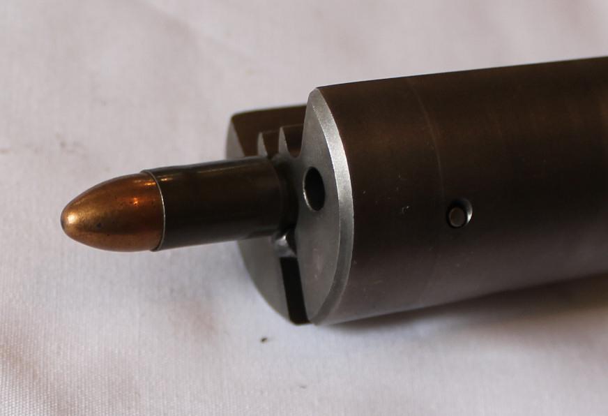
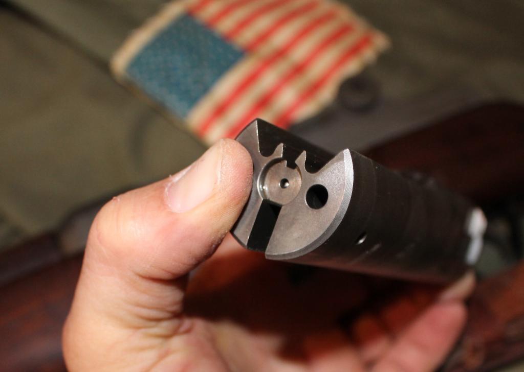
    Fitting the AR firing pin into the bolt with the spring; when the hammer is pressed fully into the recess and held, the pin does not protrude. I suspect the inertia of the hammer striking the pin pushes it through the opening in the block face and onto the base of the primer, and then the spring causes the pin to retract back beneath the face of the block.


  5. #83
    Advisory Panel browningautorifle's Avatar
    Join Date
    Jul 2008
    Last On
    Today @ 09:30 AM
    Location
    Victoria BC
    Posts
    31,178
    Real Name
    Jim
    Local Date
    07-06-2025
    Local Time
    08:54 AM
    I take it that round stock in the pic is the "Hammer" and just the inertia drives it against the firing pic...?
    Regards, Jim

  6. #84
    FREE MEMBER
    NO Posting or PM's Allowed
    17thairborne's Avatar
    Join Date
    Jan 2014
    Last On
    05-23-2023 @ 08:47 PM
    Location
    New Mexico
    Posts
    97
    Real Name
    Gorbitz
    Local Date
    07-06-2025
    Local Time
    08:54 AM
    Thread Starter
    Here is the progress for today:

    The round thingy with the 3 holes is the retainer. The three rods pass through it. Smaller rods are for the hammer spring and the recoil spring. The center rod goes into the cap in the back.

    The retainer holes are ever so slightly smaller than the diameter of the rods, so I filed the ends of the rods slightly so that they would pass through the holes by about 1/4" I then used a ball peen hammer to round the ends of the rods so they would not pull through. I only rounded them slightly because I am going to weld those in place onto the retainer.

    The large pin hole took a bit more filing to get the pin through. I used a 1/2 round file and gently nibbled away at the ID of the hole. I only used the clamp for gently holding the retainer as I did not want to squash it out of round. On my last "nibble" I took just a bit too much and the rod has perhaps .001" of play. No harm as it will also get welded. It is supposed to protrude .375" through the back of the retainer and just touch the retaining cup.

    Here is how the filing went. Keep in mind I filed in a vertical motion. the angle on the file is because I am holding the camera.


    You can see the 3 rods in place. The two smaller ones have been peened so they will not pass back through. I'll weld the ends and file them round.


    Here is the whole kaboodle placed into the IO bolt. The hammer passes through the lower rod and when the trigger is released, it will be impacted by the something-or-other and drive the firing pin into the primer.


    I could not get my extractor out of the old bolt so I had to drill the pin out. I managed to save the original extractor and spring which is fitted with a NOS pin. Here is the finished product with a Germanicon lacquered steel case round (no firing pin in the bolt)


  7. #85
    Advisory Panel
    Peter Laidler's Avatar
    Join Date
    Jul 2008
    Last On
    Yesterday @ 12:42 PM
    Location
    Abingdon, Oxfordshire. The home of MG Cars
    Posts
    16,691
    Real Name
    Peter Laidler
    Local Date
    07-06-2025
    Local Time
    04:54 PM
    The inertia firing pin is a mechanical safety feature (I expect that you are all aware of this - hopefully) that means that unless there is the full force of the hammer blow, it won't protrude with sufficient force to detonate the round. We used to do a classroom test with Browning No2 pistols to test this theory which meant dropping the pistol on the hammer to see if the FP would strike a dummy round sufficient to pop the primer. So presumably this is the safety reason for the single shot Sten to prevent an accidental discharge unless it is from a full force of a hammer blow.

    This used to raise all sorts of questions such as hard primer material etc...... This eventually caused several modifications to the hammer spring strength due to different ammunition being brought in. This included several uprated striker springs followed by ever greater hammer strength springs and so on and on. Instead of just going back to basics!

  8. #86
    Advisory Panel tiriaq's Avatar
    Join Date
    Oct 2006
    Last On
    Today @ 08:10 AM
    Location
    Central Ontario
    Age
    79
    Posts
    1,123
    Local Date
    07-06-2025
    Local Time
    11:54 AM
    The floating inertial firing pin is a BATF requirement for semi auto Stens made in the US, along with closed bolt operation. If the firing pin isn't a floater, defeating the disconnector function could result in burst fire, as the hammer follows the bolt foreword. If this were not a BATF requirement, a full length firing pin - or even a one piece hammer/firing pin would be an easier way to go. A floating inertial primer is a safety factor, but that is not why it is mandated.
    A floating, inertial firing pin will contact the primer when the bolt closes, but should not have enough energy to fire it. An example is the AR-15 type rifle - invariably if a round is ejected, there will be a slight mark on the primer. The US closed bolt semi auto Sten designs use AR-15 firing pins, no doubt because the pins are readily available at low cost.
    Some US do-it-yourself designs use a original bolt, altered for closed bolt operation and hammer or striker ignition. This requires extensive alterations, of course.
    Last edited by tiriaq; 04-12-2014 at 07:33 AM.

  9. Thank You to tiriaq For This Useful Post:


  10. #87
    FREE MEMBER
    NO Posting or PM's Allowed
    17thairborne's Avatar
    Join Date
    Jan 2014
    Last On
    05-23-2023 @ 08:47 PM
    Location
    New Mexico
    Posts
    97
    Real Name
    Gorbitz
    Local Date
    07-06-2025
    Local Time
    08:54 AM
    Thread Starter
    Thanks the great info on the firing pin. I had not considered it as either a safety feature or a BATF requirement. I sincerely appreciate the comments as I am learning much about my new weapon.

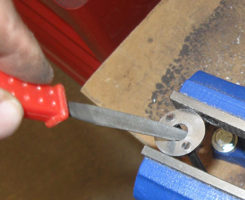
    I sized the slot in the receiver tube to the ejector, and recessed it slightly so that there will be a lip which provides room for some welded metal. That should provide a good bond between the the and the ejector. The ejector fits snugly in the slot with sufficient room between the groves on the block. I will still use paper shims between the ejector and the block during welding to prevent it from accidentally being moved.

    I also need to clean up the ejector a bit.Too many file marks on my hand made piece.

    I'm thinking of using a paper shim and a piece of aluminum foil in the groove between the block and the ejector to prevent weld splatter on the block. Sound okay?

  11. #88
    FREE MEMBER
    NO Posting or PM's Allowed
    17thairborne's Avatar
    Join Date
    Jan 2014
    Last On
    05-23-2023 @ 08:47 PM
    Location
    New Mexico
    Posts
    97
    Real Name
    Gorbitz
    Local Date
    07-06-2025
    Local Time
    08:54 AM
    Thread Starter
    Need some help here!

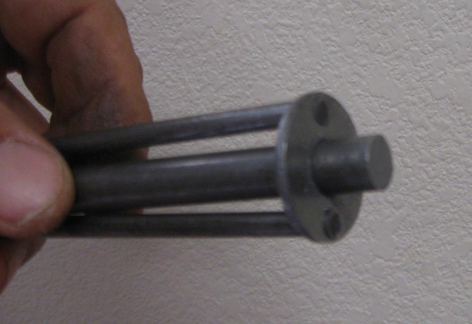
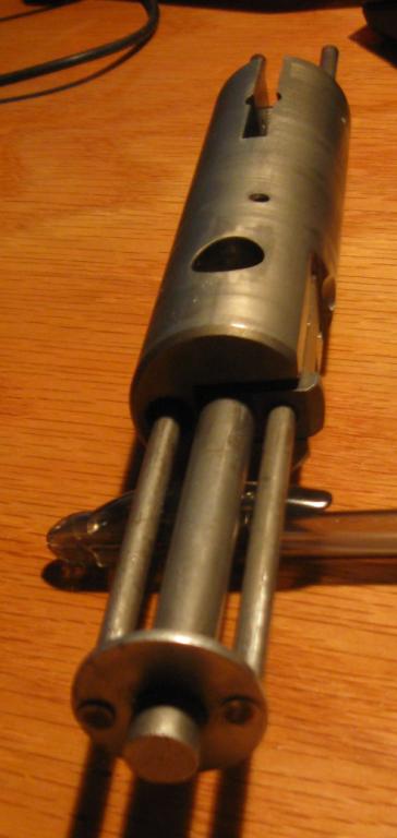
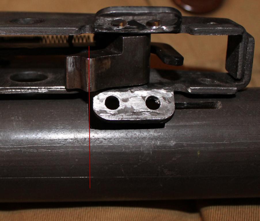
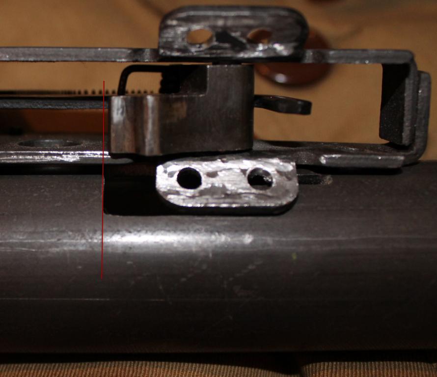
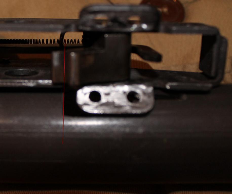
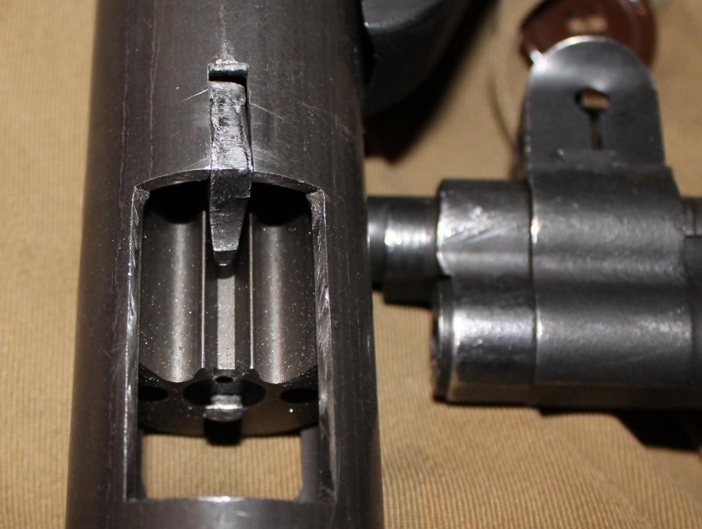
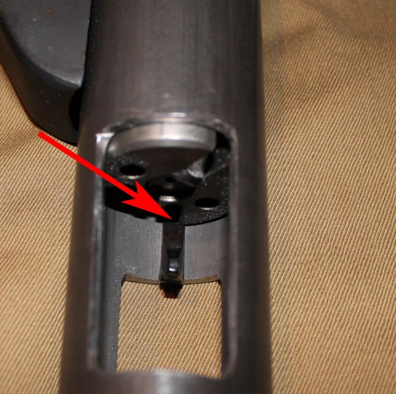
    Upon dry cycling the breech block into the safety slot on the receiver tube, I noticed the block impacts the ejector and will not go full forward into the safety slot. The images shows the problem.


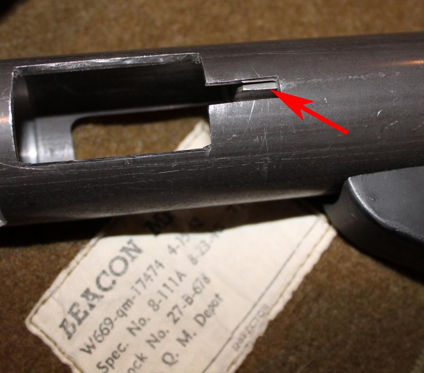
    I figure the only reasonable option is to file the ejector to make it skinnier so that the bolt grove will pass over it.

    Another option would be to file off a bit of the rear of the ejector so that when the breech moves forward and into the safety position it will not strike the ejector.

    I could also not worry about it and the bolt will just not travel fully forward when rotated upward and into the safety slot. I am concerned about this option as repeated slamming of the bolt on the ejector will cause both the bolt and ejector to wear at the point of contact.

    If I were to do this again, I would mill the safety slot about 5/16" farther aft on the tube as opposed to where it is depicted on the template.
    That way when the bolt handle is rotated upward and into the safety slot, it will be that much farther aft and not strike the ejector.

    What do you think is the best alternative to rectify this issue.

    Here's another image of the issue:

    Last edited by 17thairborne; 04-12-2014 at 11:58 AM.

  12. #89
    Advisory Panel tiriaq's Avatar
    Join Date
    Oct 2006
    Last On
    Today @ 08:10 AM
    Location
    Central Ontario
    Age
    79
    Posts
    1,123
    Local Date
    07-06-2025
    Local Time
    11:54 AM
    SAS bolt also fouls the ejector. Even prevents the bolt from going all the way into battery. Easiest to just alter the ejector to clear the bolt.
    Found this out on my first project, had to alter the ejector after it was welded in place. Much easier to do before welding.

    The safety cut in the main casing is sort of awkward to use - to rotate the bolt handle up and into the slot, the guide rods et al also have to rotate. The whole thing has to be dragged around.
    There are ways to alter the selector into a rotating or crossbolt safety.

  13. #90
    FREE MEMBER
    NO Posting or PM's Allowed
    17thairborne's Avatar
    Join Date
    Jan 2014
    Last On
    05-23-2023 @ 08:47 PM
    Location
    New Mexico
    Posts
    97
    Real Name
    Gorbitz
    Local Date
    07-06-2025
    Local Time
    08:54 AM
    Thread Starter
    Just uncovered another issue that you need to pay careful attention to when cutting the opening in the bottom of the receiver tube which allows the sear and tripping lever to function properly. If you cut the opening too far from the back of the receiver tube, the sear will not pass through it at all. That's not a problem because you can grind/file the opening bigger towards the rear of the tube so that the sear passes through, but rests on the step. If you cut the opening too far back towards the rear of the receiver tube, the entire sear will move up into the inside of the tube and you have ruined the tube. The aft measurement of the slot must be so than when the sear passes partially though the slot, it will rest on the step. Cut the slot precisely to the template, and then adjust once you dry fit the tube, trigger housing and the trigger/sear components.

    I've disassembled the tube from the lower receiver and laid it next to the slot with the trigger/sear installed so you can see the three ways to cut the slot.

    This first image shows the slot cut exactly to the template measurements. You can see how no portion of the sear will pass through the slot.


    The image below shows what would happen if I were a dumba$$ and cut/filed the slot to far aft. You can see how the entire sear including the step would pass through the slot and interfere with proper operation. This tube would be a wasted effort.


    Below is a photo showing the proper dimensions for the slot. This allows only the upper portion of the sear to pass through the slot and the step of the sear will rest on the slot. In this configuration, the trigger will be allowed to function properly: in other words, when you pull the trigger it will pull the sear downwards, releasing the spring tensioned hammer to strike the firing pin.

    Last edited by 17thairborne; 04-12-2014 at 02:03 PM.

+ Reply to Thread
Page 9 of 22 FirstFirst ... 7 8 9 10 11 19 ... LastLast

Similar Threads

  1. Starting A New 'Collection'
    By Alan de Enfield in forum The Lee Enfield Knowledge Library Collectors Forum
    Replies: 11
    Last Post: 04-06-2013, 08:24 PM
  2. The 91/30 surplus supply starting to dry up?
    By Aragorn243 in forum Soviet Bloc Rifles
    Replies: 4
    Last Post: 03-06-2012, 02:43 PM
  3. Different Starting Loads?
    By Josh Smith in forum Ammunition and Reloading for Old Milsurps
    Replies: 2
    Last Post: 09-14-2011, 03:49 PM
  4. I think you guys are starting to rub off on me
    By Rumpelhardt in forum The Lee Enfield Knowledge Library Collectors Forum
    Replies: 6
    Last Post: 08-20-2011, 07:13 AM
  5. Starting the payback!!
    By A. F Medic in forum Milsurps General Discussion Forum
    Replies: 0
    Last Post: 01-28-2010, 12:53 PM

Tags for this Thread

Posting Permissions

  • You may not post new threads
  • You may not post replies
  • You may not post attachments
  • You may not edit your posts