-
Gallery of Dramas. Broken Enfield Parts!
As a continuation of a previous thread:
Is this a common failure? by rumpelhardt
Here's some photos of failed components for your consideration. Feel free to add your own tales of woe, preferably with photos! (Even slightly fuzzy ones as some of these are-sorry! ?low batteries??? )
)
Most of the following fractures are quite "granular" in appearance, unlike typical "fatigue failure" break lines that show a combination of fracture propagation modes. Really, if there were signs of deformation surrounding the break, it would be tempting to call it ductile tension failure, but these look more like fractures found in cast iron. Note too, that most of the components are of Indian origins according to the various markings.
The cocking piece that shows the most typical appearance for a fatigue failure in steel is an Ishapore (corrected origin of mfg on 12 Dec 2010) manufactured part. Some burnishing on most of the fracture face, showing repeated cycles before failure.
Anyway, some horror pictures!:
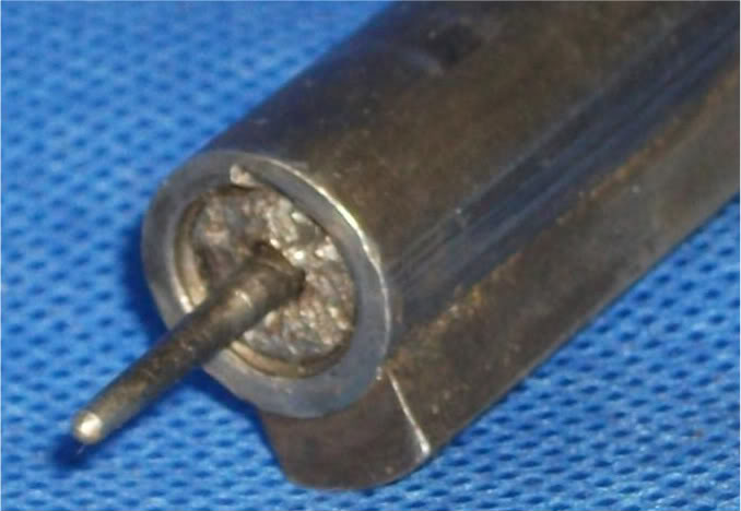
Photo#1.1-Damage on the bolt body face is due to an attempted removal of the bolt head stub.
ETA: Unfortunately, a more detailed photo won't help much here as the stub has been extensively modified in texture during some previous removal efforts.
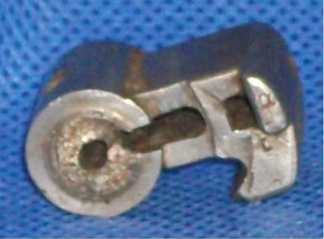
Photo #1.2a-This bolt head doesn't belong to the bolt assembly above. I've several more as well!
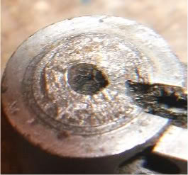
Photo #1.2b-ETA: supplemental photo as also shown in post #13.
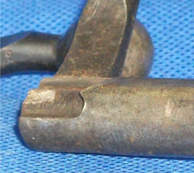
Photo #1.3a
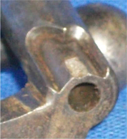
Photo #1.3b-Don't know HOW you would attempt to repair this failure! Very sad.
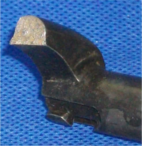
Photo #1.4a
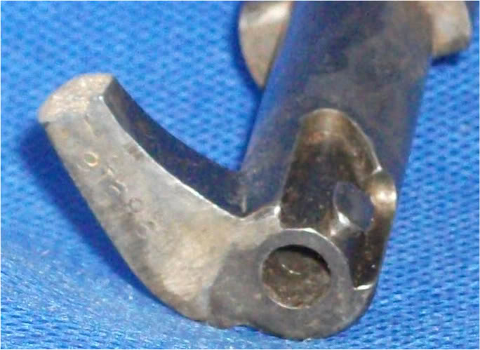
Photo #1.4b-??????
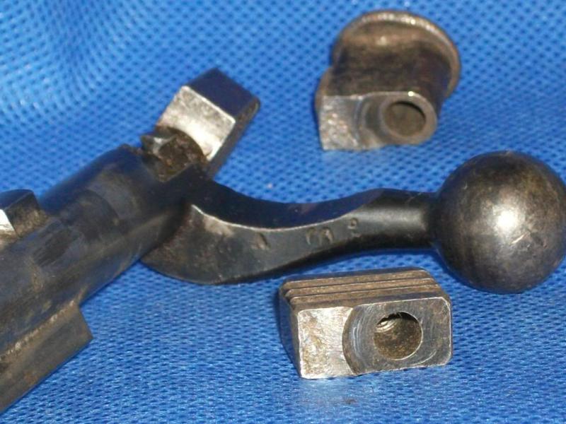
Photo #1.5-A real close up of these fracture faces would be grand. ETA- So ...there's better on post #13.
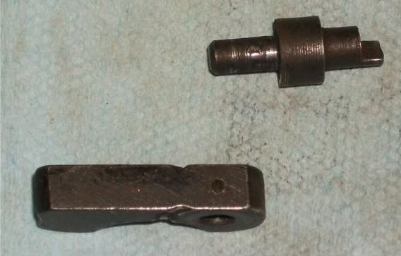
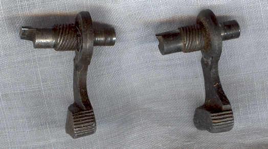
Photo #1.6- Minor failure (the cross pin) that could be fairly dangerous! Rotate the safety lever, but the cocking piece won't be restrained! Wartime emergency safety variant- worse than nothing!
Several photos leave a bit to be desired. Please give me a few days to improve the results. Hopefully, this will spark some discussion and further contributions, regardless.
No condemnation of the rifle is intended here! It's just something that I find interesting about any mechanical device- failure modes. Made a fair living dealing with it so far... and "wasted" a lot of time studying it whilst getting a degree that's hardly been used....
Information
 |
Warning: This is a relatively older thread
This discussion is older than 360 days. Some information contained in it may no longer be current. |
|
Last edited by Badger; 01-15-2011 at 06:59 AM.
Reason: Edited post to show link with description ....
-
The Following 10 Members Say Thank You to jmoore For This Useful Post:
-
12-21-2010 07:09 PM
# ADS
Friends and Sponsors

-
That bolt handle is the most interesting to me JM. That particular area is pretty well metalurgically speaking, stress free. I've never seen anything like that. It's a good clean break too. It would have been a good student project knowing what it is. The cocking pieces are unusual to me too as they usually break across the half bent/weak link. That's a hardening failure across the different mass area - yes?
-
-
I once repaired the sheered little lug on the underside of the bolt (safety lug/half cock or whatever it is) by getting a little lump welded there and then carefully filing it to the correct shape. Worked fine.
-
-
Advisory Panel


I had the unplesant opportunity to investigate and resolve? heat treat issues in the automotive business. Given the volume of fasterners Ford uses every day, it is not surprising that problems happen. Chassis Division had 7 metallurgists/material engineers alone.
Problems can be due to:
1. Improper heat treat
2. Incorrect materials or materials out of spec
3. Batch heat treat may mean parts on the out side of the heat source don't see proper temperatures or parts too close to heat may be over heated. A hardened part may not be drawn down to the final temperature. I have seen a hardend part drop on the floor and break.
4. Slag/impurities imbedded in part leads to weak cross section
5. During the milling process at the steel mill--one billet is mechanically welded to the next and the seam becomes a srtess point subject to failure in a later manufactured part.
6. Part notched or dented during manufacturing process prior to heat treat.
A coarse cross section at a break indicates an immediate failure. If the break surface is smooth with a series of curved swirls--the failure was ductile and happened over time.
I have a three inch thick textbook from a class on the Theory of Failures that attempts to cover the subject. If someone is really desperate for reading material, I can furnish the title and particulars.
-
The Following 8 Members Say Thank You to breakeyp For This Useful Post:
-
Thanks for the "Reader's Digest" version, breakeyp!
I'm thinking there's out of spec. materials dramas here, as well as heat treating issues. The cocking pieces above seem to have failed in two cases via slow crack propagation ("fatigue"), whilst the other went all at once. As it occurred in an area w/ rapid section change, it's possible heat treatment was a contributing factor, but I suspect a bit of "notch sensitivity" as well. Fairly roughly machined, most are. The Enfield example (Early type cocking piece) shows the classic crack propagation features the best (I think...they're going to be re-photoed in a few days, so maybe we'll have a better illustration.)

Originally Posted by
breakeyp

I have a three inch thick textbook from a class on the Theory of Failures that attempts to cover the subject
 Yah, I get that! I still don't know of one "bible" for this subject. Most of my best references seem to be small papers and studies. ASM and ASTM affiliated, the majority; old AWS magazines as well.
-
-
Advisory Panel
The only one I can attest to is the cocking piece (early type) broke exactly like the one pictured. About 1972 on that one.
-
-
Legacy Member

Unsafe safety
Removed from an otherwise very good condition rifle that I just got. I suppose this could ruin someone's day.
-
The Following 2 Members Say Thank You to Steve H. in N.Y. For This Useful Post:
-
Advisory Panel
Materials comments
Originally Posted by
jmoore
Thanks for the "Reader's Digest" version, breakeyp!
I'm thinking there's out of spec. materials dramas here, as well as heat treating issues. The cocking pieces above seem to have failed in two cases via slow crack propagation ("fatigue"), whilst the other went all at once. As it occurred in an area w/ rapid section change, it's possible heat treatment was a contributing factor, but I suspect a bit of "notch sensitivity" as well. Fairly roughly machined, most are. The Enfield example (Early type cocking piece) shows the classic crack propagation features the best (I think...they're going to be re-photoed in a few days, so maybe we'll have a better illustration.).
I am sure Peter can say more as he is there and knows the current British system of material callouts. The WWII period part drawings I have had access to show material callouts that allow a great variance in material components/processing. We (the US) use SAE (Society of Automotive Engineers) material descriptions. This method has become world wide much like the Doctors using Latin to provide a common language for body parts. If you call out SAE 1020 steel--it means it is made to specific ingredients and there are specific heat treat procedures to obtain a desired surface hardness and it can be expected to have specific material properties. I have seen British drawing that call out material to be a stock number from a specific supplier. If he goes out of business---you have to start over. If he makes a bad batch---how to you prove it. If he takes shortcuts due to material component unavailability, how do you prove it.
Mr. Moore I can tell you have been down the road. I had some oldtimers that helped me through the maze explaining the differences between ductile and catastrophic failures. One thing they were absolutely crazy about was if a failure was attributed to material crystalization--you got a rough lecture as all metal is crystaline in nature. Steel has infinite life, unlike Aluminum, and does not change properties over time. Steel must be worked or have a weak crossection vs. load for a failure to happen. Unlike steel, rubber continues to cure, age, over time to the point cracks/failures happen. For example look at antique car steering wheels--guaranteed cracks. Re-reading this I find that I would have been in trouble at work if I had written this. Due to the lawyers, we couldn't write using the word failure. We had to say the part was unable to react to the present load.
Yah, I get that! I still don't know of one "bible" for this subject. Most of my best references seem to be small papers and studies. ASM and ASTM affiliated, the majority; old AWS magazines as well
-
The Following 3 Members Say Thank You to breakeyp For This Useful Post:
-
Originally Posted by
breakeyp
Steel has infinite life, unlike Aluminum, and does not change properties over time.
Just a clarification on breakeyp's excellent post (He's gone to an extreme "shorthand" to keep from filling pages!):
Steel parts will theoretically survive an infinite number of stress repititions or cycles IF the applied stress is below a certain level. Above that point- failure will
happen. How soon can be predicted with increasing certainty as the variables are controlled (or are known), reducing the "factor of stupid". (A phrase I picked upfrom a favourite pre-PC professor )
)
Some parts can be designed to last millions of cycles, others don't need to last ten! It's maddenly hard to control ALL variables, though!
-
The Following 3 Members Say Thank You to jmoore For This Useful Post:
-
Legacy Member
Broken one on the right
-
The Following 2 Members Say Thank You to Mk VII For This Useful Post:


 PM
PM