+ Reply to Thread
Page 1 of 3 1 2 3 LastLast
Results 1 to 10 of 24

Thread: 1879 Remington Lee Photos, etc. (Warning! LOTS of big photos)

Click here to increase the font size Click here to reduce the font size
  1. #1
    Advisory Panel

    jmoore's Avatar
    Join Date
    Mar 2009
    Last On
    06-09-2023 @ 04:20 AM
    Location
    US of A
    Posts
    7,066
    Local Date
    03-19-2024
    Local Time
    01:41 AM

    1879 Lee (Mfg. by Remington) Photos, etc. (Warning! LOTS of big photos)

    Originally this was going to be just another magazine variation thread, but since the magazine is more dependent on the rifle for controlling the feed than later Lee mags, I figured I'd just lump it all together.

    This thread may take a while to fully "flesh out" due to time restraints on my end, so i thank you for your patience!

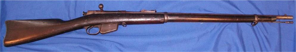
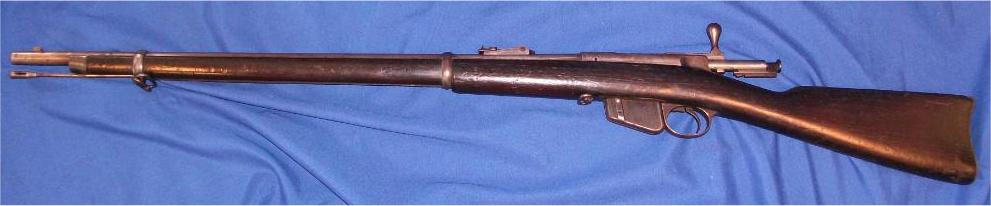
    Late ETA: Two overall photos added, finally!:


    #0a


    #0b

    To start- some photos around the receiver and mag area.


    #1 This is the father of all detachable magazine turnbolt rifles and the first Lee rifle tested by the Britishicon government for it's military potential. Certain features will survive until the end of the line!


    #2
    The cocking piece looks quite similar to the ones found on some SMLEs, but there are quite a few functional construction differences. Later Remington Lees have very different looking cocking pieces but don't stray far in concept.


    #3
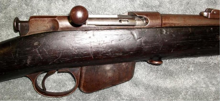
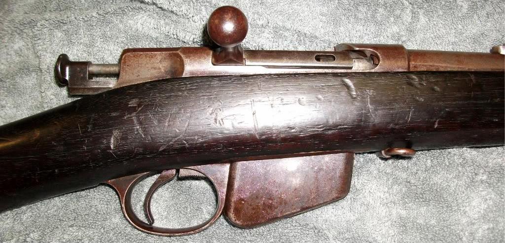
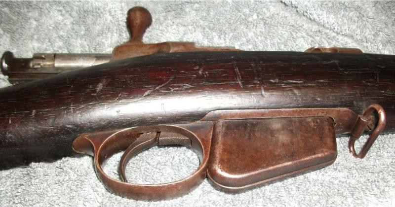
    The conveniently placed magazine release and large, gracefully shaped trigger guard are two Lee turnbolt features that will carry on. Unlike later Lee-Enfield rifles, the original concept was to issue multiple magazines for greater firepower. Loading the mag from the top is not an option. However, ease of single loading whether or not a magazine is in place was given careful consideration, as will be shown further along.


    #4

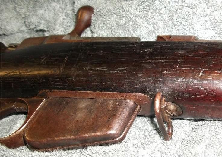
    The swivel shown here is the rear sling attachment point as there is no provision for a butt stock swivel. The loop is NOT split. The screw head itself centers the swivel as the loop's center is partially cut away where the screw head protrudes into the swivel hole. The loop must have been welded shut- just where has yet to be determined.


    #5
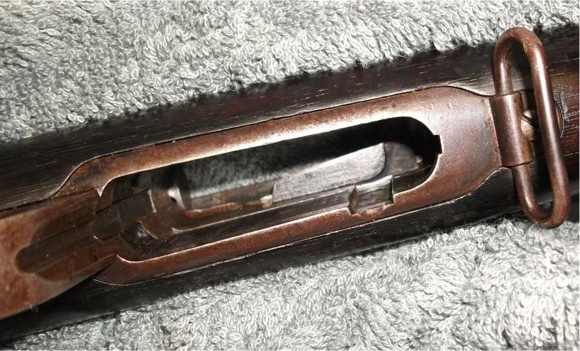
    Note the channel cut into the magazine well. This is an added feature that the first few hundred rifles lacked. The corresponding protrusion on the magazine was added in order to better retain rounds when it was not installed in the rifle.

    Also note the plate partially blocking the top of the mag. well. This spring loaded part served to act as a loading platform when firing the weapon without a magazine. It automatically moves aside when a magazine is seated.


    ---------- Post added at 03:09 AM ---------- Previous post was at 03:05 AM ----------

    First two posts were "fused" together...How odd...


    #6

    LH side view of the action. The "button" on the magazine is automatically pressed downwards when the assembly is seated in the weapon. This action serves to release the bullet nose into it's feed position. Photo #5 show a small contoured cut just outboard of the mag. well channel which cradles the button. (Nice extra touch, that.)
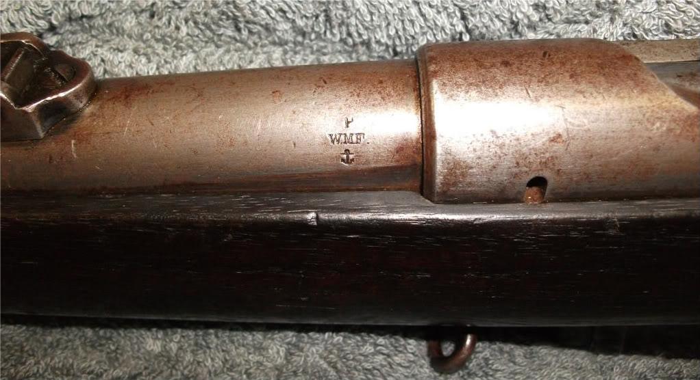

    #7

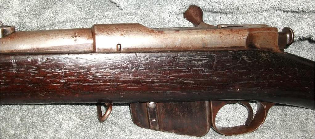
    Two main items of interest here: the U.S. Navy inspector's mark, and the emergency gas relief port cut into the left hand side of the receiver ring which is yet another feature that would carry on until the end of the line.
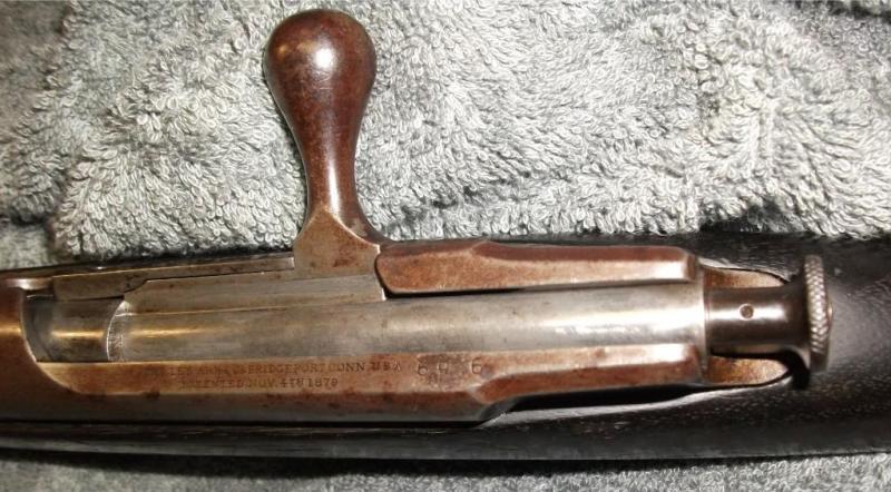

    #8
    The top rear of the receiver ring is angled to serve as the primary extraction cam. (A feature later incorporated into the Mosin Nagant design, amongst others. Is this the first appearance of this cam set-up?)

    The bolt handle placement of this model was quickly superseded in the "Model 1882" and following Lee designs. It is not as awkward as one might think, but neither is it optimal for most users.


    #9

    Serial number close-up:696
    Information
    Warning: This is a relatively older thread
    This discussion is older than 360 days. Some information contained in it may no longer be current.
    Last edited by jmoore; 01-15-2011 at 12:40 PM.

  2. The Following 3 Members Say Thank You to jmoore For This Useful Post:


  3. # ADS
    Friends and Sponsors
    Join Date
    October 2006
    Location
    Milsurps.Com
    Posts
    All Threads
    A Collector's View - The SMLE Short Magazine Lee Enfield 1903-1989. It is 300 8.5x11 inch pages with 1,000+ photo’s, most in color, and each book is serial-numbered.  Covering the SMLE from 1903 to the end of production in India in 1989 it looks at how each model differs and manufacturer differences from a collecting point of view along with the major accessories that could be attached to the rifle. For the record this is not a moneymaker, I hope just to break even, eventually, at $80/book plus shipping.  In the USA shipping is $5.00 for media mail.  I will accept PayPal, Zelle, MO and good old checks (and cash if you want to stop by for a tour!).  CLICK BANNER to send me a PM for International pricing and shipping. Manufacturer of various vintage rifle scopes for the 1903 such as our M73G4 (reproduction of the Weaver 330C) and Malcolm 8X Gen II (Unertl reproduction). Several of our scopes are used in the CMP Vintage Sniper competition on top of 1903 rifles. Brian Dick ... BDL Ltd. - Specializing in British and Commonwealth weapons Specializing in premium ammunition and reloading components. Your source for the finest in High Power Competition Gear. Here at T-bones Shipwrighting we specialise in vintage service rifle: re-barrelling, bedding, repairs, modifications and accurizing. We also provide importation services for firearms, parts and weapons, for both private or commercial businesses.
     

  4. #2
    Advisory Panel

    jmoore's Avatar
    Join Date
    Mar 2009
    Last On
    06-09-2023 @ 04:20 AM
    Location
    US of A
    Posts
    7,066
    Local Date
    03-19-2024
    Local Time
    01:41 AM
    Thread Starter

    #10

    I like the quick detach striker assembly! It is securely locked in place until removal is required, but merely needs a cartridge rim or similar to rotate the lock (just forward of the cocking piece) clockwise about 1/6 turn and free the unit.

    Note the small stud protruding from the bottom of the bolt body. This stud acts as bearing surface for the cocking cam.


    #11

    A close-up of an enduring feature: the Lee sidewall "ejector stud". In this first iteration, the ejector appears to be pressed into place. Later on, the more familiar ejector screw will perform the same function- a replaceable hard point upon which the case being removed will impact when the bolt is operated in a vigorous fashion.

    The large non-spring loaded extractor is also the bolt stop! It impacts a curved surface inboard of the RH locking face. All these years, and there's no damage. Satisfactory, I reckon. The area in question can be seen in semi-profile above.
    Last edited by jmoore; 07-24-2010 at 08:38 AM.

  5. The Following 2 Members Say Thank You to jmoore For This Useful Post:


  6. Avoid Ads - Become a Contributing Member - Click HERE
  7. #3
    Advisory Panel

    jmoore's Avatar
    Join Date
    Mar 2009
    Last On
    06-09-2023 @ 04:20 AM
    Location
    US of A
    Posts
    7,066
    Local Date
    03-19-2024
    Local Time
    01:41 AM
    Thread Starter
    Now for some mag to receiver interface photos-


    #12

    Primary intent of this photo is to show the single shot loading platform from above. Also of interest is the integral feed guide milled into the LH receiver side wall and the large cut-out on the RH rear of the receiver ring. Two functions for the latter feature- clearance for bullet noses when ejecting live rounds, and a large gas escape area in case of a massive high pressure gas leak- not uncommon in the early cartridge era, what w/ folded or "balloon" case heads and all...


    #13
    Here's the same area with the magazine inserted. The magazine can also serve as a single shot loading platform when empty.

    #14
    The underside of the rearward extension of the receiver ring serves as a cartridge guide, funneling the bullet nose into the chamber. The rifle is somewhat sensitive to the meplat form- too much of a "flat-nose" shape can hinder feed reliability. (Not a problem when there were no choices in bullets!)
    Last edited by jmoore; 07-24-2010 at 08:37 AM.

  8. The Following 2 Members Say Thank You to jmoore For This Useful Post:


  9. #4
    Advisory Panel

    jmoore's Avatar
    Join Date
    Mar 2009
    Last On
    06-09-2023 @ 04:20 AM
    Location
    US of A
    Posts
    7,066
    Local Date
    03-19-2024
    Local Time
    01:41 AM
    Thread Starter
    This post finally concentrates on the magazine.
    Next, maybe I start pulling things apart!


    #1m

    RH side view () Of particular interest are the very short feed lips at the rear of the magazine. The rounds in a loaded magazine have fairly poor retention when removed from the weapon, so soon after production started an improvement was made to address the problem, as seen below:


    #2m

    The rib on the forward LH side of the magazine body houses a strip of steel which is curved inward at the top. Its function is to prevent the bullet nose from rotating upwards and falling out of the magazine. In use, the strip's position is controlled by the button seen at the lower edge of the slot in the rib. In the "down" position, the steel strip's curved top retracts into the recess of the rib, allowing rounds to either be loaded or fed into the chamber. In the "up" position, the strip slightly curves over the cartridge, retaining it securely. This isn't a "magazine cut-off" but rather primitive solution for correcting a functional deficiency. However, it's not the last time a device like this one will be used- the same concept (minus the integral feed lips) was used effectively on the Johnson M1941, M1944, and Dror LMGs. (((Add supplemental Johnson LMG mag photos)))


    #3m

    Rear view: Main point of interest here is the simple retaining notch cut directly into the right and left body half's join seam.


    #4m

    Very simple follower, riveted onto the magazine spring.


    #5m

    When loading the magazine, as a final step, the button must be pressed upwards whilst depressing the bullet nose downward. These actions allow the cartridge retaining strip to "hook over" enough of the cartridge case that it won't pivot out of the mag. during storage and handling.


    #6m

    Profile shot if the spring and follower. Note the lack of any real sort of guidance features in the follower. It it does almost nothing to control fore and aft tilt of the ammunition.


    #7m

    A rather more "conventional" spring than in the slightly later 1882-1885 model Lees! The built-up construction avoids many production difficulties.

    Click below to view the 1882/1885 magazine and especially it's radical spring!:

    https://www.milsurps.com/showthread.php?t=22207


    #8m

    On the forward LH side of the inside of the magazine body is the cartridge retaining strip in it's retracted position. Below is a view with the strip extended. Note that the bullet will NOT be in a good feed position as the nose of the cartridge will be covered (protected?) by the front sheet metal.


    #9m

    At the rear of the magazine body, in addition to the feed lips, are pressed in guide ribs which control the case rim as it's being fed, preventing "submarining" of the round under the bolt. Too bad more magazines don't have this feature! (I've had this drama occur on more than one L-E mag...) It's merits are sufficient that the rear guide ribs are incorporated into many bolt action shotgun magazines and a current combat shotgun- the Saiga-12!


    Supplemental #1

    In production as of 2010, this is a US manufactured 10 shot Saiga-12 guage shotgun magazine that directly incorporates many features introduced in 1879. (Including the body formed in R and L halves.)


    Supplemental#2

    Note the guides formed into the inner rear of the body (close to the middle of the photo). It also has short feed lips, but being rather more stoutly constructed, this magazine doesn't need the additional forward restraint. Thus this example is even more like the very earliest Lee rifle magazine in concept!(((poorish photo- need better)))

    The major non-materials related advancement in the Saiga magazine is in the follower. It is much more sophisticated than the Lee's.
    Last edited by jmoore; 11-04-2011 at 08:07 AM.

  10. The Following 3 Members Say Thank You to jmoore For This Useful Post:


  11. #5
    Advisory Panel

    jmoore's Avatar
    Join Date
    Mar 2009
    Last On
    06-09-2023 @ 04:20 AM
    Location
    US of A
    Posts
    7,066
    Local Date
    03-19-2024
    Local Time
    01:41 AM
    Thread Starter
    Bolt parts:


    #1b

    Unlike the Lee-Enfield bolt, the early Lees could be easily stripped of all moving parts. Whilst not as "soldier-proof", this provision was much more necessary when using black powder cartridges that often leaked gasses back into the action. Found only on early Model Lees, the forward end of the bolt is integral to the body. The removable head would appear in the 1885 version.


    #2b

    Points of interest on the bolt body above, front to rear:
    1. Emergency gas escape hole just behind the bolt face. It exhausts into the relief hole on the forward left side of the receiver body. Is this the first time controlled gas venting is provided on a cartridge firearm?
    2.The large slot cut around the top and right hand side of the bolt body just forward of the rib/bolt handle base/RH locking lug is for the extractor/bolt stop. Given the relatively low working pressure of the rounds intended for this action, the loss of support is acceptable, but would not be desirable for higher intensity ammunition.
    3.The large rib on the RH side of the body serves not only as a guide during cycling, but as the attachment point for the extractor retainer. It's also the bolt handle base and RH locking lug. (you determine the order of importance!)
    4.LH locking lug
    5.Cocking piece cam pin. Just a theory, but I'm wondering if the cam wasn't made into the bolt body proper, at first, in order to simplify manufacture. One small hole, a pre-hardened pin, and less dedicated or precise tooling would be required to go this route. In view of the many other efficiencies found in the design, my idea may be completely off base...Comments welcomed!


    #3b

    The striker, striker spring and cocking piece won't change in execution much throughout the entire line of Lee turnbolt rifles. The lugged retaining collar, however, isn't seen again on Lee designs. Not a bad idea, though. What other firearms use this QD striker system?

    The purpose of the small vertical hole in the cocking piece eludes me for now. There's no corresponding hole through the striker, so it's not or a locking pin. Any ideas?

    Note that the cocking piece guide and guide cutout at the rear of the bolt body perform no other function at this point.


    #4b

    Note the wrenching flats on the striker forward of the spring seat collar. In the case of this rifle, no tools were required to unscrew the assembly.

    Below the striker front end are the extractor retainer on the left and the extractor on the right. There is no extractor spring, as such, but the retainer adds a spring like action when the extractor attempts to pivot. Explanation might get a bit lengthy, but basically, the retainer pushes downwards on the top of the extractor, forcing it to maintain close contact w/ the bolt body. (((This odd feature might deserve a whole post or two on it's own.)))


    #5b


    #6b


    #7b
    Last edited by jmoore; 11-04-2011 at 08:36 AM.

  12. The Following 5 Members Say Thank You to jmoore For This Useful Post:


  13. #6
    Advisory Panel

    jmoore's Avatar
    Join Date
    Mar 2009
    Last On
    06-09-2023 @ 04:20 AM
    Location
    US of A
    Posts
    7,066
    Local Date
    03-19-2024
    Local Time
    01:41 AM
    Thread Starter
    Receiver body and stock bedding photos-


    #1r
    Note that the split boss for the sear and magazine catch retaining pins also serves as the recoil lugs when bedded in the stock. If the wood sets back due to recoil or other rearward impacts (droppage or bayonet usage come to mind), there's not a lot of surface area to keep the action's rear tang from shifting back and splitting the stock. Perhaps this is the type of breakage that concerned the Britishicon evaluators. Thus, the L-E two piece stock! Purely conjecture on my part, but more plausible than a "weak wrist" which this rifle DOESN'T have!


    #2r
    Certain design points were so good from the start they really never changed! The magazine catch and the "U" shaped spring keep their same format throughout the entire Lee turnbolt family. Sear design changed, mostly in minor details, with a couple of evolutionary dead-ends thrown into it's lineage.


    #3r


    #4r
    It's kind of surprising how much metal was removed to accomodate the single shot loading platform. Given the novel technology of quick reloading box magazines, and the reluctance of the U.S. military to issue "ammunition wasting" repeaters, it surely was worth the effort, if only from a sales standpoint.


    #5r


    #5a


    #6r


    #7r


    #8r
    Today, I look at the stock inletting and immediately think how easy it would be to glass this type action in a precision rifle build. Give it a front recoil lug and go to town!


    As a warning, any commentary made to date has been w/o references and done sporadically, so don't be alarmed at errors and lack of cohesiveness! (Even a year and 4+ months later it's still a work in progress...)
    Last edited by jmoore; 11-04-2011 at 08:15 AM. Reason: tweaking

  14. The Following 8 Members Say Thank You to jmoore For This Useful Post:


  15. #7
    Legacy Member Emri's Avatar
    Join Date
    Mar 2009
    Last On
    03-10-2022 @ 09:10 AM
    Location
    Alabama Gulf Coast
    Posts
    479
    Local Date
    03-18-2024
    Local Time
    11:41 PM
    "The purpose of the small vertical hole in the cocking piece eludes me for now. There's no corresponding hole through the striker, so it's not for a locking pin. Any ideas?"

    Probably an air escape hole. In that time period grease was used rather than oil. If too much was in a blind hole, when the firing pin was screwed in it could hinder proper seating at the bottom. Excess grease could escape through the small hole.

    "Note the wrenching flats on the striker forward of the spring seat collar. In the case of this rifle, no tools were required to unscrew the assembly."

    It looks like the extractor retainer could be used as a "tool" to unscrew the striker (firing pin). The slot in it looks very close to the same size as the flats in your pic. Does it fit?

    "The top rear of the receiver ring is angled to serve as the primary extraction cam. (A feature later incorporated into the Mosin Nagant design, amongst others. Is this the first appearance of this cam set-up?)"

    In bolt action rifles? I don't know. My 1865 Springfield "Joslyn" rifle has a cam that serves to initiate extraction when the breech block is opened.


    Thank you for this very informative posting! Though I knew what the rifles were from past studies, I have never had the chance to disassemble one and study any individual pieces of it. Postings like this are what I would like to see more of.


    Thanks again,

    Emri

  16. #8
    Advisory Panel smellie's Avatar
    Join Date
    Jan 2008
    Last On
    01-14-2019 @ 09:17 AM
    Location
    Virden, Man. Pop 3250, 4 miles from Wolverine's range!
    Posts
    632
    Local Date
    03-19-2024
    Local Time
    01:41 AM
    Before this, there was only Lee's original handmade rifle.

    Lee originally contracted with Sharps' to have his rifle produced, but they went broke before completion of the job. Remington finished the first lot of rifles and hired Lee to sell Rolling Blocks for them, which he accomplished in vast number.

    I have never had a chance to examine closely an original Remington-Lee rifle; they just do not seem to exist in my part of the world.... and I have never had the money to purchase even a junker, although I certainly would have had the opportunity raised its head. THIS SERIES of photogaphs is ALMOST as good as having one on the table in front of me. I wish to express my sincere thanks for this series of posts; it was a great deal of work but it IS appreciated very much.

    ONE query: would it be possible to post a couple of photos of critical parts with a Ruler as part of the photo? Alternately, can you supply any critical dimensions?

    The truly AMAZING thing I find is that, looking through my Number 4 parts kit (about half of an Armourer's kit, borrowed from Long Branch many years ago) is the sheer number of parts which changed only slightly in dimensions, not at all in function, right to the very end.

    My vote for Best Rifle Designer of the Nineteenth Century goes to James Paris Lee.

    Again, my thanks for this superb series.

  17. #9
    Advisory Panel

    jmoore's Avatar
    Join Date
    Mar 2009
    Last On
    06-09-2023 @ 04:20 AM
    Location
    US of A
    Posts
    7,066
    Local Date
    03-19-2024
    Local Time
    01:41 AM
    Thread Starter
    What parts do you wish to be photographed w/ a scale in the frame? I'd rather not do another major pull-apart until the next shooting session- which may not be any time soon!

    If the muzzle was a bit stronger I'd try and work up some good accurate BP loads. No way it's going to get recrowned whilst i have it!

    Sorry that I kind of left this thread orphaned for a while- too much going on otherwise! Will try and flesh it out some more as the opportunity presents itself.


    ETA 04 Oct 2010 (and 2011!). Started adding some more commentary -captions actually- to the photo spread. Feel free to comment or ask questions! I need some prodding along at times.
    Last edited by jmoore; 11-04-2011 at 08:17 AM.

  18. #10
    FREE MEMBER
    NO Posting or PM's Allowed
    Story's Avatar
    Join Date
    Feb 2007
    Last On
    10-19-2019 @ 07:35 PM
    Posts
    12
    Local Date
    03-19-2024
    Local Time
    01:41 AM
    Quote Originally Posted by jmoore View Post
    Serial number close-up:696
    Five years ago I had a sporterized First Contract with a serial # not so far off from yours.
    Amazon.com: The Remington-Lee rifle (9781880677049): Eugene Myszkowski: Books

    As near as I could figure, they went to either the armored cruisers USS Boston & Atlanta.
    Cruiser Boston

    I could never find enough parts to even start a restoration and that's before I appreciated sporters for what they were.

    I always wondered whether the USNavy archives had either cruiser's logs from the time period when they took delivery, which might have listed the serial numbers.

+ Reply to Thread
Page 1 of 3 1 2 3 LastLast

Similar Threads

  1. Link to photos of 1885 Remington Lee magazine
    By jmoore in forum The Lee Enfield Knowledge Library Collectors Forum
    Replies: 0
    Last Post: 06-15-2010, 08:46 AM
  2. Model 10 Remington trench warfare photos !
    By Mark Baker in forum Military Shotguns
    Replies: 1
    Last Post: 08-17-2009, 10:52 AM
  3. Remington #16,136 photos.
    By Lancebear in forum Pattern 1913/1914 and M1917 Rifles
    Replies: 10
    Last Post: 03-23-2009, 07:30 PM
  4. New old Remington 1917 photos.
    By Lancebear in forum Pattern 1913/1914 and M1917 Rifles
    Replies: 8
    Last Post: 03-21-2009, 02:28 AM

Tags for this Thread

Posting Permissions

  • You may not post new threads
  • You may not post replies
  • You may not post attachments
  • You may not edit your posts
Raven Rocks