


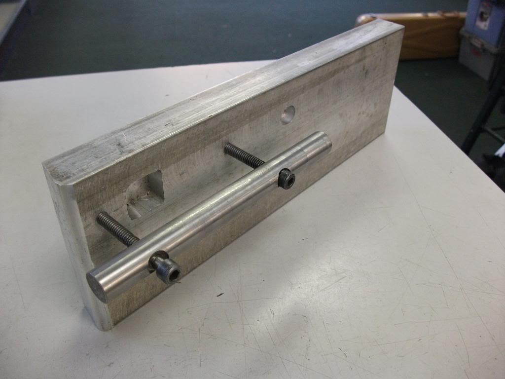
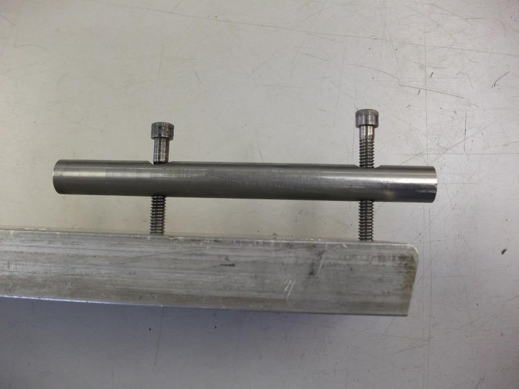
I've used this plate for repair work:
Arbor is barely a slip fit into the action body's raceway.
But H&H apparently set their primary datum using centers that engaged the bore at either end. The whole works mounted on an old lathe bed. I would have to think that they also incorporated a rotational datum and locking mechanism. Which probably stabilized the action body whilst the several milling operations were done. If they had the room and equipment it would seem logical that the spigot and the rear pad angles milling operations were done on another machine, but they may have just had multiple quick change (belt driven, probably, so less weight) milling heads. Five operations for sure: Front pad flat. Rear pad flat. Front pad angle. Then, after pads attached: Front spigot, rear angles.
The holes could have been generated using a drill jig or two with appropriate bushings. Would be as accurate or more as doing it on the milling set-up.
The real drama for folk building fanasty rifles is that the available pads have had the "after installation" cuts already done. Which makes getting proper alignment way more difficult than as originally conceived. Which is why I haven't done much yet with the old lathe I have stored for doing the "correct" way...Information

Warning: This is a relatively older thread
This discussion is older than 360 days. Some information contained in it may no longer be current.
- Knowledge Library

- MKL Entry of the Month
- Australia
- Austro-Hungarian Empire
- Canada
- Czechoslovakia
- Denmark
- Finland
- France/Belgium
- Germany
- Italy
- Japan
- Norway
- Russia
- South America
- Sweden
- Switzerland
- Turkey
- United Kingdom
- United States
- Yugoslavia
- Is my rifle authentic or a fake?
- Jay Currah's Lee Enfield Web Site
- On-line Service Records (Canada)
- Technical Articles/Research
- Forum
- Classifieds
- What's New?
-
Photo Gallery
- Photo Gallery Options
- Photo Gallery Home
- Search Photo Gallery List
-
Photo Gallery Search
- Video Club
- iTrader
 PM
PM