-
Legacy Member

No4T pad jig
Thank you to everyone for all the info and sharing of wisdom on this site. As a Gunsmith I find it very refreshing to look on here and see the varied different ways people approach things.
I am doing a couple L42 projects for a customer and feel this would be a good time to build the jig for installing the pads. Does anyone have a print with the measurements for the jig?
Thanks again
Dave
Information
 |
Warning: This is a relatively older thread
This discussion is older than 360 days. Some information contained in it may no longer be current. |
|
-
-
10-02-2014 07:50 AM
# ADS
Friends and Sponsors

-
FREE MEMBER
NO Posting or PM's Allowed

There is a series of blueprints of the original mounts on the site. And an original mount might provide the basis for a jig for fitting the pads.
-
Maybe the very FIRST thing you ought to do is to read a short series on making a T replica. L42/No4T the principles are the same. A jig is OK so far as it goes but not all the rifle bodies are the same and it's NOT the bodies that the pads, the bracket and subsequently the telescope are aligned with. It's the optical axis of the telescope and the mechanical centre line of the bore.
-
-
Legacy Member
I have read your excellent sources of info. The main reason I would like the jig is for its work holding features. I believe that big plate of steel would secure the action very nicely while performing the rest of the work.
Dave
-
-
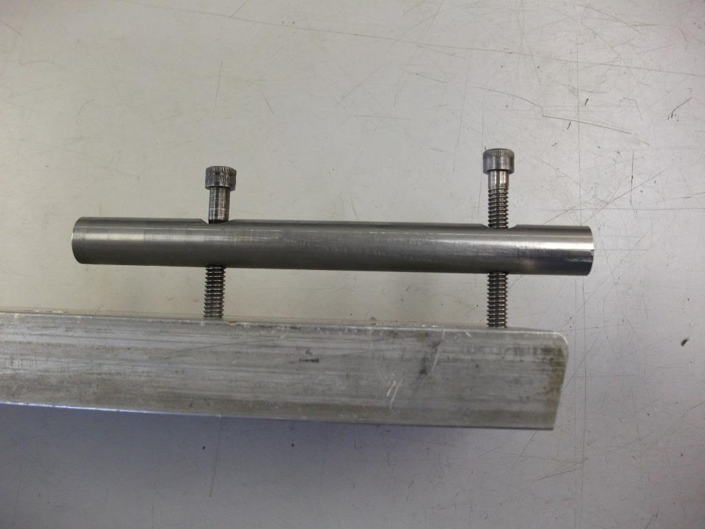
I've used this plate for repair work:
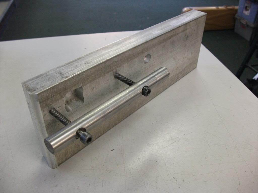
Arbor is barely a slip fit into the action body's raceway.
But H&H apparently set their primary datum using centers that engaged the bore at either end. The whole works mounted on an old lathe bed. I would have to think that they also incorporated a rotational datum and locking mechanism. Which probably stabilized the action body whilst the several milling operations were done. If they had the room and equipment it would seem logical that the spigot and the rear pad angles milling operations were done on another machine, but they may have just had multiple quick change (belt driven, probably, so less weight) milling heads. Five operations for sure: Front pad flat. Rear pad flat. Front pad angle. Then, after pads attached: Front spigot, rear angles.
The holes could have been generated using a drill jig or two with appropriate bushings. Would be as accurate or more as doing it on the milling set-up.
The real drama for folk building fanasty rifles is that the available pads have had the "after installation" cuts already done. Which makes getting proper alignment way more difficult than as originally conceived. Which is why I haven't done much yet with the old lathe I have stored for doing the "correct" way...
Last edited by jmoore; 10-03-2014 at 03:05 AM.
-
Thank You to jmoore For This Useful Post:
-
Legacy Member

I would talk to Roger Payne about his pads and bracket if you haven't already got them. His are the best available.
-
-
Advisory Panel

Methodology would depend on whether one had access to CNC machinery or not. If not, digital readout would certainly make repeatability much easier, if both pads were done on one mill. A long table or a rigid jig would be needed to hold the barreled receiver. Rear pad contact area on the receiver wall would not need to be machined normally.
“There are invisible rulers who control the destinies of millions. It is not generally realized to what extent the words and actions of our most influential public men are dictated by shrewd persons operating behind the scenes.”
Edward Bernays, 1928
Much changes, much remains the same. 
-
-
Legacy Member
Wonderful. Thanks gents!
Dave
-


 PM
PM