-
Legacy Member


Plate for Machining No.4 Bodies
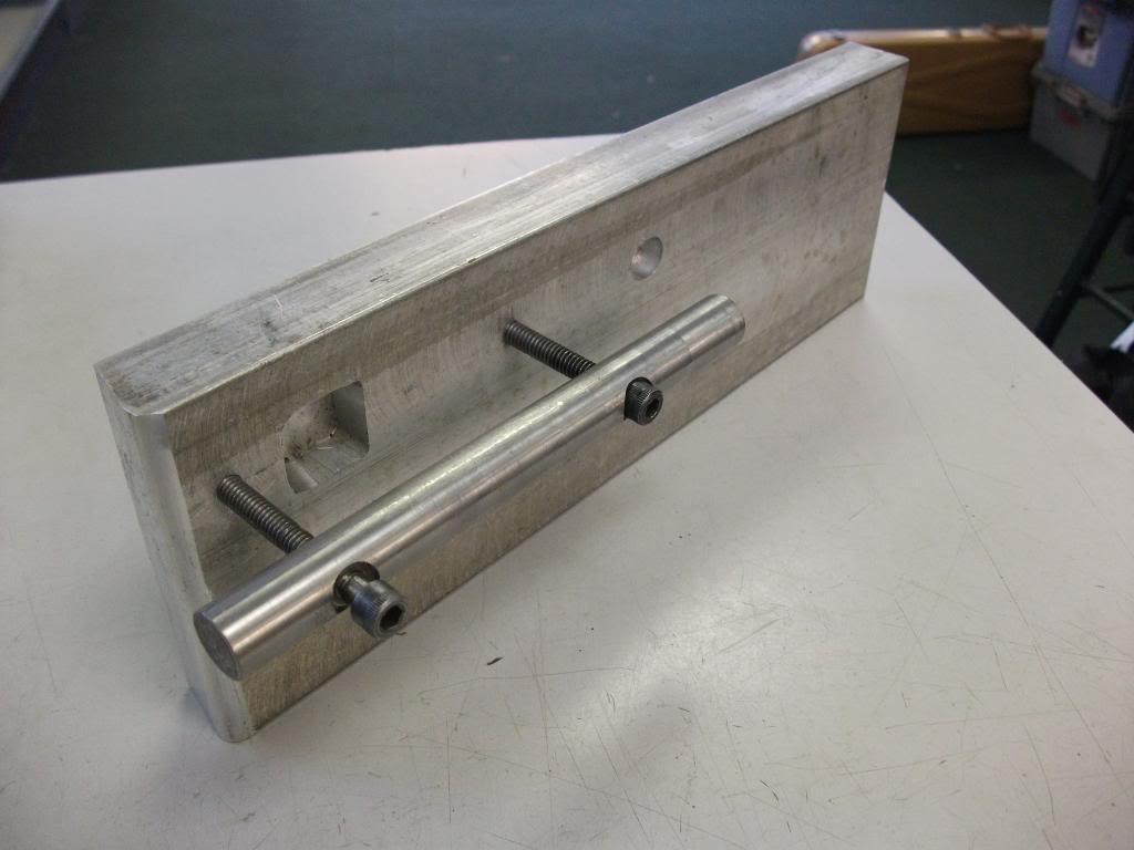
"How to make a useable sniper - Part 2" contains pictures of a plate used to hold No. 4 bodies square, for machining and engraving.
Having recently experienced a "gunsmith" stuff up the mounting of pads on one of my rifles, I am wanting to duplicate the above plate.
I have unsuccessfully searched for dimensions.
Assistance in helping me find/determine the dimensions will be appreciated.
Cheers
Paul
Information
 |
Warning: This is a relatively older thread
This discussion is older than 360 days. Some information contained in it may no longer be current. |
|
-
Thank You to paulseamus For This Useful Post:
-
04-29-2012 08:56 AM
# ADS
Friends and Sponsors

-
FREE MEMBER
NO Posting or PM's Allowed

when you buying the milling machine?
cheers
Ned
-
-
You won't find dimensions anywhere. Each of the big workshops would make hundreds of jigs for machining, welding, engraving, breeching-up and everything else you could possibly think of. It was just one used for engraving that held the body both square to and parallel and at the same time, parallel to the vice/pantograph jaws
-
-
Legacy Member

You need a competent toolmaker.
-
Thank You to Homer For This Useful Post:
-
-
The Following 2 Members Say Thank You to jmoore For This Useful Post:
-
FREE MEMBER
NO Posting or PM's Allowed

Peter,
Maybe I'm just thick as a whale omlet here, but you're saying that all the jigs you guys knocked up were just measured off the weapon being worked on & cut in the workshops on an as-needed basis?
Cheers
-
Legacy Member

Back in the day they had plenty of machinists who were competent to design and make this sort of stuff, which was usually better than whatever tools the ordnance establishment supplied. Now I doubt anyone would be allowed to, as it isn't ISO9001, or whatever it's called now. Can't have units actually fixing their own problems, we have to generate $$ for defence contractors.
-
-
Legacy Member


Originally Posted by
Longshaor

Maybe I'm just thick as a whale omlet
May I borrow that line? I am not even sure what a whale omlet is but I like it!
-
-
FREE MEMBER
NO Posting or PM's Allowed


Originally Posted by
HOOKED ON HISTORY

May I borrow that line?
I borrowed it from Blackadder the Third. It was just too good not to perpetuate!
-

Originally Posted by
Longshaor

Peter,
Maybe I'm just thick as a whale omlet here, but you're saying that all the jigs you guys knocked up were just measured off the weapon being worked on & cut in the workshops on an as-needed basis?
Cheers
From what I've read of Peter Laidler 's experience and research, the primary data were the bore and the rear sight axis pin hole. fore and aft placement of the pads was allowed a bit of flexiblity to ensure sufficient thread engagement of the rear pad. Apparently, Hollands adapted an old lathe bed for doing the milling and drilling work. Handy, I suppose, for the ease of using centers at either end. Photos of their device would be most interesting. There's an old lathe in storage that might get the same treatment just for funsies one day!
ETA1: (in dribs and drabs): To truly locate the pads off the bore axes, the muzzle end is pretty obvious- just use a bronze center. (Brownell's sells them in packs of five as they don't last long, but better damage to the center than the muzzle!) The rear end is a bit of a conundrum. To be exact, a range rod would have to be run in from the breech end, but would do nothing more than locate. Stabilizing the action body would be done by other means altogether. More support could be obtained at the expense of locating accuracy by utilizing a sort of chamber plug that wedges at the rear of the chamber. Least accurate but most stable (and what I've done for my repair plate) is to use a snug fitting action rod with a locating center at the rear of the rod.
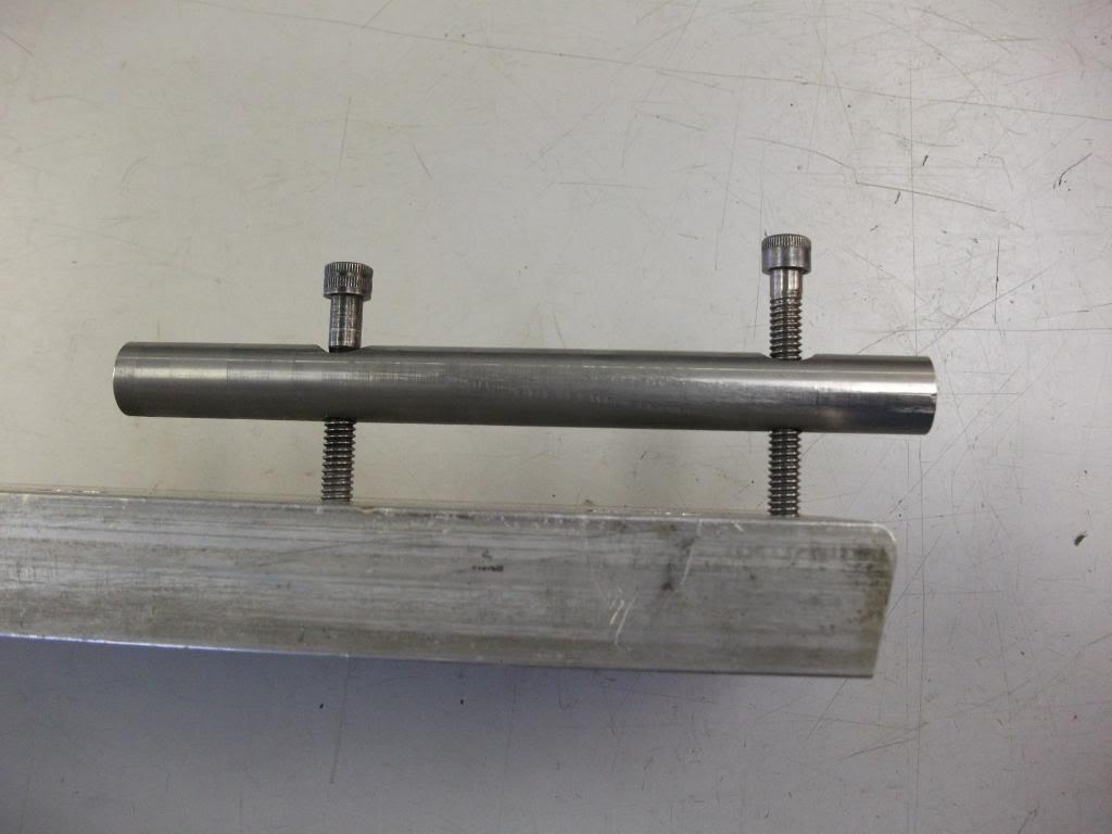
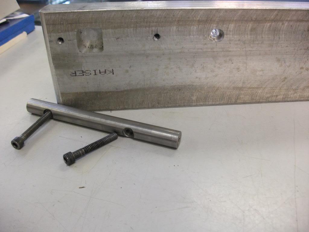
The plate shown above was made for repair of loose pads, sheared spigots and such. (First use was to add dowel pins during a loose pad repair for an L42a1 that had a hard time with the night vision gear.)
[ETA3: The plate isn't really a locating devise. It's just there to stabilize the aligned assembly so it doesn't move whilst work is being done. The bottom of the action body is probably a manufacturing datum plane, but nothing references off of it for the purposes of scope mounting! At best it might serve as "c" or rotational axis locator, but if the sight axis pin happened to walk during manufacture, then "up" in the scope and "up" for the iron sights won't match.] ETA1continued: As far as doing a set of pads from scratch- Not yet! But I'd rather do them the way Hollands did- by forming the spigot and angle cuts after the pads were installed. (Shell mill cutter would have to be made for the spigot. I don't know if something is available that could be used or adapted without going the full "custom cutter" route, but that's an option, too!)
ETA2: Just a SWAG, but I reckon the rifle was installed on H&H's converted lathe and the spigot and rear pad were cut in less than fifteen minutes cycle time. Probably closer to 6-7 minutes to install, cut, and remove once they had the system tweaked.
Last edited by jmoore; 05-01-2012 at 04:15 AM.
-


 PM
PM


